The Veethree display is a versatile electronic device designed for monitoring various parameters in marine and industrial applications. It comes in several series, including T-Series (touch screen color displays), R-Series (round housing displays), C-Series (color displays), and M-Series (monochrome displays), each offering different form factors and functionalities to suit diverse needs.
Function Description:
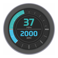
The primary function of the Veethree display is to provide real-time visual feedback on critical operational data. Depending on the model and configuration, it can display information such as engine RPM, speed (MPH), water temperature (°C), battery voltage (volts), and other sensor readings. The displays are designed to integrate with CAN (Controller Area Network) protocols, allowing them to communicate with various engine management systems and other networked devices. Some models also feature USB ports for external I/O, RS232/RS422/RS485 communication, and digital/analogue inputs/outputs for expanded functionality. The touch screen models (T-Series) offer an intuitive user interface for easy navigation and data interaction.
Important Technical Specifications:
Mounting:
- Designed for mounting onto a bulkhead, dashboard, or panel.
- Mounting hole templates are available for precise installation.
- Overall size (for round displays): 95mm (3.74") x 95mm (3.74").
- Fixing Hole Positions (for round displays): 70mm (2.75") x 70mm (2.75").
- Cut Out for back recess (for round displays): 86mm diameter (3.39").
- Drill 4mm clearance holes (x4) for mounting studs: 4.3mm (0.17").
- Mounting uses threaded studs and thumb nuts; hand-tightening only to prevent damage.
Power Supply:
- Power (10-32V DC) supply.
- Should be protected by a 500mA-rated circuit breaker/fuse (for C3/C3i/C7 models).
Connectors (Vary by model):
T7i / T5 (External USB IO & Ethernet):
- CAN1 & CAN2 (5-pin Deutsch connector):
- Pin 1: No Connection
- Pin 2: Positive DC Supply (CAN1), Isolated Volts Positive (CAN2)
- Pin 3: Ground (CAN1), Isolated Volts Negative (CAN2)
- Pin 4: CAN Data H
- Pin 5: CAN Data L
- External USB IO (12-pin Deutsch connector):
- Pin 1: USB Volts Positive
- Pin 2: USB Data Negative (DM)
- Pin 3: USB Data Positive (DP)
- Pin 4: No Connection
- Pin 5: USB Volts Negative
- Pin 6: RS422/485 Tx+*
- Pin 7: RS422/485 Tx-*
- Pin 8: RS422/485 Rx+*
- Pin 9: RS422/485 Rx-*
- Pin 10: Digital Input
- Pin 11: Analogue Input
- Pin 12: Relay Output
- *RS422 and RS485 options configured as a build option.
- Ethernet (4-pin Deutsch connector):
- Pin 1: White/Orange +TK
- Pin 2: White/Green +RX
- Pin 3: Orange - TX
- Pin 4: Green
R3 / R3s (Primary & Secondary Connectors - 12-pin Deutsch connector):
- R3 Primary Connector:
- Pin 1: Ground
- Pin 2: Power Input
- Pin 3: Dimmer Input
- Pin 4: Analogue in 1
- Pin 5: CAN Ground
- Pin 6: CAN Power
- Pin 7: NMEA 2000 / J1939 - CAN H
- Pin 8: NMEA 2000 / J1939 - CAN L
- Pin 9: NMEA 0183+ (Differential)
- Pin 10: NMEA 0183- (Differential)
- Pin 11: Power Supply (Output for GPS)
- Pin 12: Ground Supply (Output for GPS)
- R3 Secondary Connector:
- Pin 1: Analogue - Ground
- Pin 2: Digital Out 1 (Relay / Buzzer)
- Pin 3: Analogue in 2
- Pin 4: Analogue in 3
- Pin 5: Analogue in 4
- Pin 6: Analogue in 5
- Pin 7: Analogue in 6
- Pin 8: Digital Input 1
- Pin 9: Digital Input 2
- Pin 10: Digital Input 3
- Pin 11: Digital Input 4
- Pin 12: Frequency Input
- R3s Primary Connector:
- Pin 1: Ground
- Pin 2: Power Input
- Pin 3: Relay Output 1
- Pin 4: Relay Output 2
- Pin 5: CAN Ground - isolated CAN Supply (-)
- Pin 6: CAN Power - isolated CAN supply (+)
- Pin 7: CAN H - isolated CAN Data H
- Pin 8: CAN L - isolated CAN Data C
- Pin 9: Relay Output 3
- Pin 10: Relay Output 4
- Pin 11: Primary CAN Data L
- Pin 12: Primary CAN Data H
C7 (Primary, Secondary, Tertiary Connectors - 12-pin Deutsch connector):
- Primary Connector:
- Pin 1: Ground
- Pin 2: Power (10-32V DC) Supply (protected by 500mA circuit breaker/fuse)
- Pin 3: Relay / Solenoid Output 1
- Pin 4: Relay / Solenoid Output 2
- Pin 5: Isolated CAN Supply (-)
- Pin 6: Isolated CAN Supply (+)
- Pin 7: Isolated CAN Data H
- Pin 8: Isolated CAN Data L
- Pin 9: Relay / Solenoid Output 3
- Pin 10: Relay / Solenoid Output 4
- Pin 11: Primary CAN Data L
- Pin 12: Primary CAN Data H
- Secondary Connector:
- Pin 1: Sensor 1 Analogue Input
- Pin 2: Sensor 2 Analogue Input
- Pin 3: Sensor 3 Analogue Input
- Pin 4: Sensor 4 Analogue Input
- Pin 5: Sensor 5 Analogue Input
- Pin 6: Sensor 6 Analogue Input
- Pin 7: Sensor 7 Analogue Input
- Pin 8: Digital Input / Flow Sensor 1
- Pin 9: Digital Input / Flow Sensor 2
- Pin 10: Tachometer Input
- Pin 11: RS232 Receiver
- Pin 12: RS232 Transmit
- Tertiary Connector:
- Pin 1: Sensor 8 Analogue Input
- Pin 2: Sensor 9 Analogue Input
- Pin 3: Sensor 10 Analogue Input
- Pin 4: Sensor 11 Analogue Input
- Pin 5: Sensor 12 Analogue Input
- Pin 6: Sensor 13 Analogue Input
- Pin 7: Sensor 14 Analogue Input
- Pin 8: Digital Input / Flow Sensor 3
- Pin 9: Relay / Solenoid Output 5
- Pin 10: Relay / Solenoid Output 6
- Pin 11: Relay / Solenoid Output 7
- Pin 12: Relay / Solenoid Output 8
C3 / C3i / C3il (Primary & Secondary Connectors - 12-pin Deutsch connector):
- C3 Primary Connector:
- Pin 1: Ground
- Pin 2: Power (10-32V DC) Supply (protected by 500mA circuit breaker/fuse)
- Pin 3: Relay / Solenoid Output 1
- Pin 4: Relay / Solenoid Output 2
- Pin 5: Isolated CAN Supply (-)
- Pin 6: Isolated CAN Supply (+)
- Pin 7: Isolated CAN Data H
- Pin 8: Isolated CAN Data L
- Pin 9: Relay / Solenoid Output 3
- Pin 10: Relay / Solenoid Output 4
- Pin 11: Primary CAN Data H
- Pin 12: Primary CAN Data L
- C3 Secondary Connector:
- Pin 1: Sensor 1 - analogue input
- Pin 2: Sensor 2 - analogue input
- Pin 3: Sensor 3 - analogue input
- Pin 4: Sensor 4 - analogue input
- Pin 5: Sensor 5 - analogue input
- Pin 6: Sensor 6 - analogue input
- Pin 7: Sensor 7 - analogue input
- Pin 8: Digital input / flow sensor 1
- Pin 9: Digital input / flow sensor 2
- Pin 10: Tachometer input
- Pin 11: RS232 Receiver
- Pin 12: RS232 Transmit
- C3i / C3il Primary Connector:
- Pin 1: Power - Ground
- Pin 2: Power (10-32V DC) Supply (protected by 500mA circuit breaker/fuse)
- Pin 3: RS232 Transmit
- Pin 4: Ground
- Pin 5: Ground
- Pin 6: RS232 Receive
- Pin 7: CAN Data L
- Pin 8: CAN Data H
- Pin 9: Not Used
- Pin 10: Not Used
- Pin 11: Not Used
- Pin 12: Not Used
M2 (6-pin Deutsch connector):
- Pin 1: Ground
- Pin 2: Power
- Pin 3: CAN - H
- Pin 4: CAN - L
- Pin 5: Relay / Digital - OUT
- Pin 6: Analogue - IN
M4 (12-pin Deutsch connector):
- Pin 1: Power -ve
- Pin 2: Power +ve
- Pin 3: RS232 TX (+)
- Pin 4: RS232 TX (-)
- Pin 5: RS232 RX (-)
- Pin 6: RS232 RX (+)
- Pin 7: CAN LO
- Pin 8: CAN HI
- Pin 9: J1708 / J1587A
- Pin 10: J1708 / J1587A
- Pin 11: Switched Output (261 only)
- Pin 12: Not used
Compliance:
- CE EMC Directive 2004/108/EC compliant (ensured by correct installation).
Usage Features:
- Easy Installation: Units are designed for straightforward mounting onto dashboards or panels. Templates are provided to assist with cutting the mounting hole.
- Secure Connections: Connectors are designed to latch securely, ensuring reliable data and power transmission.
- Network Compatibility: The displays are compatible with various CAN network protocols, allowing integration into existing systems. Veethree offers support for specific network topography questions.
- Data Display: Clear and intuitive display of critical parameters such as speed, RPM, temperature, and battery voltage. Touch screen models enhance user interaction.
- Expandability: Multiple input/output options (digital, analogue, relay, RS232/422/485) allow for connection to a wide range of sensors and external equipment.
- Safety Warnings: Important safety notes regarding over-tightening mounting studs, using metal screws, and exceeding analogue input voltage limits are provided to prevent damage and voiding warranty. USB ports are not to be used for charging external equipment.
Maintenance Features:
- Minimal Maintenance: No regular maintenance is required beyond cleaning the lens.
- Cleaning: The lens should be cleaned with a soft, damp cloth. Abrasive materials or solvents should not be used.
- Troubleshooting Guide: A comprehensive troubleshooting section is included to address common issues such as:
- Unit does not power up: Check connections and power source.
- Unit fails to display any data: Verify connections, ensure data source is broadcasting, confirm display's source address matches data, and check backbone connection/terminating resistors.
- Unit displays random data: Check connections and ensure "demo mode" is off.
- Servicing Access: Adequate clearance behind the display is recommended during installation to allow for easy removal for servicing.
- Continuous Improvement: Veethree operates a policy of continuous improvement, reserving the right to alter and improve displays and software without prior notice.