Do you have a question about the Veichi AC70T series and is the answer not in the manual?
Ensures safe, reliable, and reasonable use by understanding safety precautions.
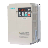
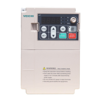
Details input/output, performance, and basic functions of the inverter.
Precautions and requirements for safe and reliable inverter installation and wiring.
Highlights dangers and warnings related to basic inverter operations.
Covers parameter initialization, run commands, and frequency command instructions.
Details methods and instructions for automatic motor parameter tuning.
Explains the built-in brake control function and its control timing.
Describes function, cautions, and parameters for brake failure protection.
Details the activation, working process, and parameters for brake torque detection.
Explains constant power control for load-adaptive speed to improve efficiency.
Describes smooth lifting for hoist operations to prevent 'nodding' phenomena.
| Frequency Range | 0~600Hz |
|---|---|
| Cooling Method | Forced air cooling |
| Enclosure Rating | IP20 |
| Input Voltage | Three-phase AC 380V±15% |
| Output Voltage | 0~Rated Input Voltage |
| Control Mode | V/F control |
| Overload Capacity | 150% rated current 60s; 180% rated current 10s |
| Braking Unit | Built-in braking unit |
| Communication | RS485 |
| Protection Features | Over-current, over-voltage, under-voltage, overload, overheat, phase loss |
| Operating Temperature | -10°C to +40°C |
| Storage Temperature | -20°C to +60°C |
| Ambient Humidity | 5% to 95% RH, non-condensing |