EasyManua.ls Logo

Veichi AC200-L Series User Manual

Veichi AC200-L Series
42 pages
To Next Page IconTo Next Page
Page #1 background imageLoading...
Page #1 background image
1
CONTENTS
1.0 SCHEMATICDIAGRAMAND INSTALLATIONDIMENSIONS..........................................1
1.1 SCHE MATICDIAGRAM............................................................................................................2
1.2 INSTALLATIONDIM ENSIONSOFTHEINVERTER(UNIT :MM)...........................................................3
2.0 WORKINGPRINCIPLE.................................................................................................5
2.1 FEEDBACKPOLARITYRANGEDETE CTIO N....................................................................................5
2.2 JOGINCHINGLEADS.............................................................................................................5
2.3 COILDIAMETERCALC ULATIONKVALUEAUT OMATICCALCULA TION................................................5
2.4 MECHANICALTRANSMISS IONRATIO.........................................................................................5
2.5 COILDIAMETERRESET...........................................................................................................5
2.6 RECOMMENDEDCONTROLWIRING..........................................................................................5
3.0 FUNCTIONTABLE........................................................................................................6
4.0 DETAILEDDE SCRIP TIONOFFUNCTIONPARAMETERS..............................................31
4.1 DET AILEDDE SCRIPTIONOFSWITCHTER MINALPARAMETERGROUP..............................................31
4.2 DET AILEDDE SCRIPTIONOFSPEC IALFUNCTIONPARAMETERS.......................................................33
4.3 MONITORING CODE............................................................................................................38
5.0 PARAMETERSETTINGREFERE NCE............................................................................39
5.1 RECOMMENDEDPARAMETE RSOFSTRAIGHTWIREDRA WINGMACH INE........................................39
5.2 RECOMMENDEDPARAMETE RSOFWA TERTANKTYPEDUA LFREQUENCYCONVERSIONHOST(WIRE
DRA WINGMACHIN E
).........................................................................................................................40
5.3 RECOMMENDEDPARAMETE RSOFWA TERTANKTYPEDOUBLEFREQUENCYCONVERSIONTAKEUP
MACHINE
40
6.0 DEBUG GINGOFSPE CIALIN VER TERFORWIREDRA W INGMACHINE .......................41
6.1 WIRINGOFHOS TANDTAKEUP MACHINE...............................................................................41
6.2 TAKEUPMACHINEFEEDBA CKCONNECTION .............................................................................41
6.3 BRAKINGRESISTORWIRING..................................................................................................41
6.4 DISCONNECTIO NDETECTIONFUNCTION.................................................................................41
6.5 BRAKECONTROL.................................................................................................................42
Question and Answer IconNeed help?

Do you have a question about the Veichi AC200-L Series and is the answer not in the manual?

Veichi AC200-L Series Specifications

General IconGeneral
Cooling MethodForced air cooling
Enclosure RatingIP20
Input Voltage3-phase 380V ±15%
Output Voltage0~Rated Input Voltage
Input Frequency50/60Hz
Output Frequency0~600Hz
Control ModeV/F control
Power Range0.4kW
Rated Output CurrentDepends on model
Overload Capacity150% for 60 seconds, 180% for 10 seconds
Protection FeaturesOvercurrent, overvoltage, undervoltage, overload, overheat, short circuit
Communication InterfacesRS485, Modbus
Operating Temperature-10°C to +50°C
Storage Temperature-20°C to 60°C
AltitudeLess than 1000m (Derating if above 1000m)

Summary

1.0 SCHEMATIC DIAGRAM AND INSTALLATION DIMENSIONS

1.1 SCHEMATIC DIAGRAM

Illustrates the wire drawing machine's control diagram with frequency conversion.

1.2 INSTALLATION DIMENSIONS OF THE INVERTER (UNIT: MM)

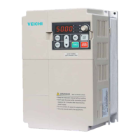
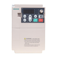
Provides physical dimensions and mounting hole specifications for inverter models.

2.0 WORKING PRINCIPLE

2.1 FEEDBACK POLARITY RANGE DETECTION

Describes setting the tension balance bar feedback for optimal PID control.

2.2 JOG INCHING LEADS

Details settings for jog and inching operation frequency and acceleration/deceleration times.

2.3 COIL DIAMETER CALCULATION K VALUE AUTOMATIC CALCULATION

Explains the automatic calculation of winding diameter for constant tension.

2.4 MECHANICAL TRANSMISSION RATIO

Defines mechanical transmission ratio and its importance for drawing effect.

2.5 COIL DIAMETER RESET

Explains resetting winding diameter for synchronization when changing coils.

2.6 RECOMMENDED CONTROL WIRING

Details recommended wiring connections for host and take-up machines.

3.0 FUNCTION TABLE

4.0 DETAILED DESCRIPTION OF FUNCTION PARAMETERS

4.1 Detailed description of switch terminal parameter group

Describes the functions and settings of multi-function input and output terminals.

4.2 Detailed description of special function parameters

Details various special function parameters for wire drawing machine control.

4.3 MONITORING CODE

Lists monitoring codes for checking inverter status and parameters.

5.0 Parameter setting reference

5.1 Recommended parameters of straight wire drawing machine

Provides recommended parameter settings for straight wire drawing machines.

5.2 Recommended parameters of water tank type dual frequency conversion host (wire drawing machine)

Offers recommended parameter settings for water tank type dual frequency hosts.

5.3 Recommended parameters of water tank type double frequency conversion take-up machine

Provides recommended parameter settings for water tank type double frequency take-up machines.

6.0 Debugging of special inverter for wire drawing machine

6.1 Wiring of host and take-up machine

Explains wiring connections between the host and take-up frequency converters.

6.2 Take up machine feedback connection

Details connecting the tension balance bar potentiometer for feedback.

6.3 Braking resistor wiring

Describes the necessity and wiring of an external braking resistor.

6.4 Disconnection detection function

Explains how the inverter detects and handles line disconnection faults.

6.5 Brake control

Details the control logic for activating the brake signal and its timing.

Related product manuals