Do you have a question about the Veichi SD710 Series and is the answer not in the manual?
Explains safety precautions for installation, wiring, operation, maintenance, and inspection.
Details items to confirm regarding the product upon receipt, including model and damage checks.
Provides guidelines on proper handling and storage to prevent damage, electric shock, or fire.
Outlines precautions to take during product installation, focusing on environmental conditions and physical placement.
Details critical precautions to follow during wiring to prevent injury, fire, or damage to the drive.
Lists safety precautions to observe during the servo motor's operation to prevent injury or malfunction.
Describes necessary precautions before performing maintenance or inspection tasks on the servo drive.
Covers the maintenance and inspection procedures for the servo unit, including motors and drives.
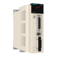
Introduces the servo drive and its basic components.
Explains how to interpret the servo drive's nameplate and model description for identification.
Details the various components and connectors found on the servo drive unit.
Lists the electrical and basic specifications of the servo drive, including voltage, current, and environmental conditions.
Provides specifications related to the servo drive's braking resistors, including voltage and resistance values.
Details the physical dimensions and mounting hole specifications for the drive.
Introduces the servo motor and its naming convention.
Explains the structure and meaning of the servo motor model naming.
Identifies and describes the key parts of the servo motor.
Lists the mechanical and electrical specifications of the servo motors.
Details the allowable axial and radial loads for the motor to prevent damage.
Provides electrical specifications for the gate motor, including holding torque and supply voltage.
Lists mounting dimensions for various servo motor flange sizes.
Describes how to match cables with servo drive and motor models.
Details the naming convention and specifications for motor power cables.
Provides information on encoder cable naming, number of lines, and length.
Details the naming convention and specifications for motor braking cables.
Outlines configurations for servo systems, showing drive, motor, and matching cable combinations.
Describes the terminal pin distribution for the servo driver.
Explains the main circuit connection for the servo driver, including terminal descriptions.
Provides examples of wiring for both built-in and external braking resistors.
Specifies recommended types and specifications for main circuit connection cables.
Illustrates an example of single-phase 220V main circuit power wiring.
Discusses important considerations for main circuit wiring to ensure safety and performance.
Lists power distribution specifications for peripherals connected to the main circuit.
Details the procedure for wiring spring-type terminals used in servo drives.
Describes the servo driver output and motor connection for power cables.
Details the schematic diagram for servo driver and encoder connections.
Explains the communication wiring diagram and pin definitions for CN6A and CN6B.
Illustrates the pin definition for the multi-function CN1 terminal.
Describes the position command input signals, including pin numbers and functions.
Details the digital input and output signals and their pin assignments.
Provides wiring diagrams for digital input circuits using internal or external power supplies.
Illustrates circuit diagrams for digital output control using relays or optocoupler devices.
Specifies the encoder frequency division output signal specifications.
Explains wiring for the brake input signal and holding brake considerations.
Provides measures to suppress interference in electrical wiring and grounding.
Shows an example of wiring and grounding treatment for resistance against interference.
Explains the proper procedures for installing and using noise filters.
Lists precautions for using cables, focusing on bending, tension, and cable protection chains.
Provides typical wiring examples for position control.
Identifies the panel operator keys and their respective functions.
Explains how to switch between different functions using the MODE/SET button.
Details how to interpret the status displayed on the panel, including abbreviated symbols and showing numbers.
Describes how to operate auxiliary functions using point-and-click operations on the panel.
Explains how to write parameters, covering value setting and functional selection methods.
Details the procedure for writing parameters using the value setting type.
Explains how to write parameters for functions that are selected based on specific conditions.
Describes the method for writing switching parameters, breaking down bit settings.
Provides a step-by-step guide on setting parameters, covering different digit lengths.
Explains how to set parameters with values less than five digits, including positive and negative numbers.
Details how to set parameters with values exceeding five digits, as the panel only displays five digits.
Explains how to set function codes for functions that are selected based on the panel operator display number.
Covers initial basic settings and pre-operation checks to ensure safe and proper motor operation.
Lists essential checks to perform before powering up the servo system to ensure safety and functionality.
Describes the procedure for turning on the power and verifying the servo drive's operational state.
Explains how input and output terminals can be configured using function codes, including external and virtual terminals.
Provides an example of configuring terminal X1 as the servo enable signal.
Demonstrates an example of operating switching outputs, including terminal configuration and monitoring.
Shows examples of using virtual terminals for input and output operations.
Explains the JOG test run function for confirming servo motor rotation without a host computer.
Details JOG mode for speed control, using set parameters for speed and acceleration/deceleration.
Describes Program JOG operation for continuous running via pre-set modes, distance, and timing.
Explains how to set the motor's direction of rotation and frequency division output pulse.
Details the function of the holding brake mechanism and its settings.
Covers the overtravel prevention function that uses limit switch signals to stop the motor.
Discusses transient and continuous overloads, including warning detection time.
Explains how to limit output torque for machine protection and the methods for torque limiting.
Describes different methods for stopping the servo motor in case of Gr.1, Gr.2 alarms, or overtravel.
Details the regenerative brake setting, especially concerning external regenerative resistors.
Introduces location control, which uses position commands for precise motor positioning.
Explains how to select the position command source using function code Pn200.
Describes how to select command pulse filters based on pulse frequency to prevent abnormal pulse reception.
Explains how the input multiplier of position command pulses can be switched.
Details the various forms of pulse input supported by the servo unit.
Provides the formula and routine for setting electronic gear ratios to match machine reduction ratios.
Explains the use of the deviation clear signal (/CLR) to clear the servo driver pulse deviation counter.
Describes the function to disable command pulse input counting during position control.
Covers the positioning proximity (NEAR) signal used in position control for preparing subsequent actions.
Explains the signal indicating the completion of servo motor positioning (COIN).
Details the function to filter command pulses for smoother motor rotation.
Describes the encoder divider pulse output, which provides position information.
Provides an example of position control operation using PLC linear differential output pulses.
Explains the speed command source selection using internal registers.
Summarizes the speed command sources supported by the product using internal registers.
Details the soft start function, which converts step speed commands into smoother acceleration/deceleration.
Explains the zero speed clamp function for performing servo lock when the speed command is below a threshold.
Describes the switching rotation detection signal (/TGON) output based on motor speed.
Covers the speed agreement signal (/V-CMP) output when motor speed is within the target speed threshold.
Provides examples of speed control operations using internal function codes and external terminals.
Explains the internal setting torque function for controlling torque operation using pre-set commands.
Summarizes the internal setting torque function for performing torque control operations.
Details the function to limit servo motor speed to protect the machine during torque control.
Explains the torque single trigger function, which involves locking processes and torque/speed limits.
Provides examples of internal torque operation and internal torque mixing operation.
Describes hybrid control modes that allow switching between different control methods.
Outlines basic settings for hybrid control modes, including control mode selection signals.
Briefly mentions speed/position control mode selection.
Briefly mentions torque/position control mode selection.
Briefly mentions speed/torque control mode selection.
Briefly mentions speed/position/torque control mode selection.
Covers the use of multi-turn absolute encoders for constructing absolute value checkout systems.
Details the procedure for installing a battery unit for saving absolute encoder position data.
Explains methods for reading absolute values of multi-turn encoders via PLC communication or DI/DO terminals.
Provides a procedure for replacing the absolute encoder battery if voltage is low.
Discusses how the number of revolutions can exceed the encoder's upper limit over time.
Lists important precautions to consider before performing servo unit adjustments.
Explains that tuning optimizes responsiveness by adjusting servo gain parameters.
Highlights safety precautions for servo unit protection functions during adjustment.
Describes the adjustment-free function for automatic stable response regardless of machinery type or load fluctuations.
Introduces the adjustment-free function that allows automatic stable response.
Lists parameters that become invalid when the adjustment-free function is active.
Details the steps for operating the adjustment-free function, including setting rigidity and load inertia.
Explains the smart settings function for automatic servo drive adjustment based on mechanical characteristics.
Summarizes the intelligent setting function, which automatically adjusts the servo drive based on mechanical characteristics.
Outlines pre-implementation recognition matters and examples of adjustments that may fail or not perform smoothly.
Describes one-touch tuning for adjusting servo gain by inputting speed or position commands.
Explains how to adjust servo gain parameters by understanding the drive's composition and characteristics.
Provides example steps for adjusting servo gain, including torque command filter, speed loop, and position loop gains.
Details the gain switching function, including manual and automatic switching methods.
Explains the speed feedforward function for improving positioning time during position control.
Describes torque feedforward for improving torque command response and reducing position deviation.
Explains PI-P control switching for speed and position modes.
Details the friction compensation function for compensating viscous friction variations and fixed load variations.
Explains the function to slow down mechanical oscillation after positioning commands are completed.
Lists auxiliary functions available for servo motor trial operation, adjustment, and information inquiry.
Explains how to search historical fault information, displaying up to ten generated alarms.
Details the function to clear alarm records of the servo drive, which cannot be cleared by normal alarm reset.
Describes the software reset function used to reset the servo driver when parameters need to be turned back on.
Explains the function used for restoring parameters to their factory settings.
Describes JOG operation for confirming servo motor action by speed control without a host unit.
Explains Program JOG operation for continuous operation via pre-set modes, distance, and timing.
Details the function to write motor-related parameters to the serial encoder EEPROM.
Explains the procedure for setting (initializing) the absolute encoder, especially for initial machine start.
Describes the auxiliary function used to prevent inadvertent parameter changes and restrict auxiliary functions.
Explains how to display motor model information, including code, power, and current ratings.
Details how to display the software versions of the MCU and FPGA.
Explains how to display servo drive model information and query rated current.
Covers the auxiliary function for identifying the initial motor zero position.
Describes the adjustment-free function for obtaining a stable response through automatic adjustment.
Explains the intelligent adjustment function that automatically tunes the servo drive without connecting to the upper unit.
Details the intelligent adjustment function that tunes the servo drive based on mechanical characteristics while receiving commands from the host computer.
Explains how to clear drive faults using this auxiliary function, applicable to resettable faults.
Describes the function to improve vibration suppression effect through single parameter tuning.
Explains how to force output signals from the servo drive's output terminal (Y) for debugging.
Details how to clear the pulse counter value for monitoring function code Un006.
Explains how to clear the encoder feedback counter for zero processing.
Describes the one-touch tuning method for automatically adjusting servo gain by inputting commands.
Explains how to store current multi-turn absolute position information to function codes Pn296 and Pn297.
Details how to set left and right limit positions using internal encoder values in the absence of external limit switches.
Explains how to set the Tamagawa encoder's over-temperature alarm threshold.
Describes the EasyFFT function for detecting resonant frequencies and setting notch filters.
Explains how to monitor vibration during operation and automatically set notch filters or torque command filters.
Lists monitoring displays numbered with Un, used for displaying input/output signals and related information.
Illustrates how to read 16-bit data decimal displays using Un000 as an example.
Details how to read 32-bit data decimal displays using Un008 as an example.
Explains how to view input signal status in the CN1 terminal using Un100.
Provides the procedure for displaying input signals (SI).
Explains how to interpret the lighted status of the drive's panel operator's digital tube for input signals.
Describes how to view output signal (Y) status in the CN1 terminal using Un101.
Provides the procedure for displaying output signals (Y).
Explains how the lighted status of the panel operator's digital tube indicates output signal status.
Shows how to display absolute encoder position information, including calculations for encoder units.
Lists monitoring function codes that can be cleared for practical use.
Provides detailed descriptions of specific monitoring function codes like Un00B.
Describes basic parameters including function selection, control mode, and drive/motor types.
Details parameters related to servo gain adjustment, including proportional and integration gains for speed and position loops.
Covers parameters related to position control, such as command source, filtering, multiplier, and gear ratios.
Lists parameters related to speed control, including speed command source, filtering, and soft start settings.
Details parameters related to torque control, including torque limiting methods and trigger settings.
Lists auxiliary parameters related to JOG operations and program JOG settings.
Describes parameters for configuring input and output terminals, including filtering and function assignments.
Covers extended parameters related to vibration suppression, motor identification, and encoder settings.
Details parameters for motion control, including internal position, speed, and torque modes, and home position return methods.
Lists parameters related to servo model selection, power, and voltage levels for communication.
Covers parameters related to motor specifications, including encoder type, power, current, and inertia.
Addresses pre-operation faults and warnings, focusing on issues preventing servo enablement.
Details troubleshooting steps for situations where the servo cannot be enabled, indicated by "nrd" status.
Covers operating exceptions in position mode after the servo is enabled, such as motor not rotating or reversing.
Addresses operating exceptions in speed mode, including issues with speed command entry or rotation.
Discusses abnormal operations in torque mode, such as motor not rotating or reversing with torque commands.
Provides guidance on handling faults and warnings that occur during servo operation.
Classifies servo faults and warnings into Category 1 (Gr.1) and Category 2 (Gr.2) and explains fault reset methods.
Explains how to view fault and warning logs, including methods via auxiliary function Fn000 or monitoring codes.
Describes how the servo can output current fault or warning signal flags.
Explains how to query historical fault information using auxiliary function Fn000 or monitoring parameters.
Details how to monitor parameters for information related to fault occurrences for troubleshooting.
Lists common fault codes, their names, classification, and whether they can be reset.
Lists common warning messages, their descriptions, and the conditions under which they occur.
Provides reasons and handling measures for various unusual alarms, including parameter exceptions and servo failures.
Details the Modbus protocol used for servo drive communication via the 485 interface.
Explains the Modbus communication protocol, including transmission modes, baud rates, and data frame formats.
Lists function codes related to communication settings, such as local address and baud rate.
Describes the register address mapping function for reading/writing addresses without changing PLC programs.
Covers Canopen communication, including performance parameters and network configuration.
Lists performance parameters for Canopen communication, such as baud rate and maximum number of stations.
Details network parameter configuration, including communication object identifiers and system parameter settings.
Explains the Communication Object Identifier (COB-ID) and its composition.
Outlines system parameter settings required for servo drive access to the Canopen fieldbus network.
Describes Network Management System (NMT) services for initializing, starting, and stopping the network.
Explains how nodes send emergency messages when failures occur and how the servo drive acts as an emergency message producer.
Details the different control modes supported by the servo drive, including profile position, speed, and torque.
Explains profile position mode where the master sends target position, speed, and acceleration/deceleration data.
Describes profile speed mode where the master transmits target speed, acceleration, and deceleration time.
Explains profile torque mode where the master sends target torque and torque ramp constant.
Details the home position return mode for finding the mechanical home and locating the position relative to the mechanical zero point.
Covers interpolated position mode where the master sends position values every synchronization cycle.
Provides detailed descriptions of object properties and lists cluster objects.
Explains terms like Index, Data type, and Read/Write Type used in the object dictionary.
Lists objects within the 1000h cluster, including equipment type and error registers.
Lists objects within the 6000h cluster, covering control words, status words, and operating modes.
Provides detailed descriptions for objects in the 1000h cluster, such as error registers and manufacturer details.
Offers detailed descriptions for objects in the 6000h cluster, including control words and status words.
Introduces the concept of home position return, defining home position and zero point.
Explains the home position return process and signal sources.
Provides an overview of different home position return methods based on signal sources and deceleration points.
Details home position return method 0 in forward direction, covering running routes and signal logic.
Explains home position return method 2 in forward direction, utilizing home position switch and Z signal.
Describes home position return method 4 in forward direction, using limit switches for deceleration and home position.
Details home position return method 6 in forward direction, using forward limit switch and Z signal.
Explains home position return method 8 in forward direction, using Z signal for deceleration and stopping.
Covers home position return method 10 for running to the absolute position using multi-turn absolute encoders.
Introduces internal multi-segment position control, covering basic settings and operation methods.
Lists basic internal position settings, including control mode and command source selection.
Describes internal multi-segment position operation modes: single segment, single-time multi-segment, and cyclic multi-segment.
Details functional operating parameters for internal multi-segment position control.
Explains single-segment position operation, including terminal and communication triggers.
Describes single continuous run operation, where the process starts from Pr1 and runs once per trigger.
Explains cyclic continuous operation, where the process runs from Pr1 to the end segment and repeats.
Details sequential operation, where the sequence runs from Pr1 to Pr4 or a specified segment based on Pn804.
Defines the functions assigned to input terminals X1 through X9, including trigger methods and control modes.
Defines the functions assigned to output terminals Y1 through Y5, including trigger methods and control modes.
| Brand | Veichi |
|---|---|
| Model | SD710 Series |
| Category | Servo Drives |
| Language | English |