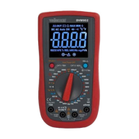
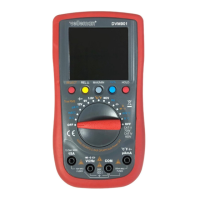
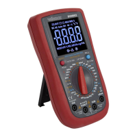
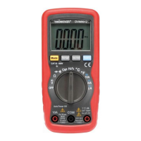
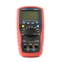
DVM902
V. 02 – 29/01/2020 13 ©Velleman nv
10. Operation
10.1 DC + AC VOLTAGE MEASUREMENT
Do not measure circuits that may contain voltages > 700 VDC or
> 700 VAC
Use extreme caution when measuring voltages higher than 60 VDC
or 30 VAC rms.
Always place your fingers behind the protective edges of the test
probes while measuring!
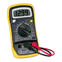
1. Set the rotary switch in the desired “ ” or “ ” position.
2. Connect the red test lead to the “VHz” jack and the black lead to the
“COM” jack.
3. Press SELECT to choose the “DC” or “AC” measurement.
4. Connect the test leads to the source being measured.
5. Read the voltage value and the polarity of the red test lead on the LCD
display.
6. On the AC range, press “Hz/%” to measure frequency or duty cycle.
Notes
• If the range is not known beforehand, set the selector switch to a high
range and lower gradually.
• An OVER-RANGE is indicated by OL or -OL. Set to a higher range.
• The maximum input voltage is 700 V rms.
10.2 DC CURRENT MEASUREMENT
Do not measure circuits that may contain voltages > 700 VDC or
> 700 VAC
Use extreme caution when measuring voltages higher than 60 VDC
or 30 VAC rms.
Always place your fingers behind the protective edges of the test
probes while measuring!
1. Set the rotary switch in the desired “ ”, “ ” or “ ” position.
2. Connect the red test lead to the “µAmA” jack and the black test lead to
the “COM” jack (switch the red lead to the “15A” jack for
measurements between 600 mA and 15 A).
3. Press SELECT to choose the “DC” or “AC” measurement.
4. Open the circuit in which the current is to be measured and connect
the test leads to the circuit IN SERIES.
5. Read the current value and the polarity of the red lead connection on
the LCD display.