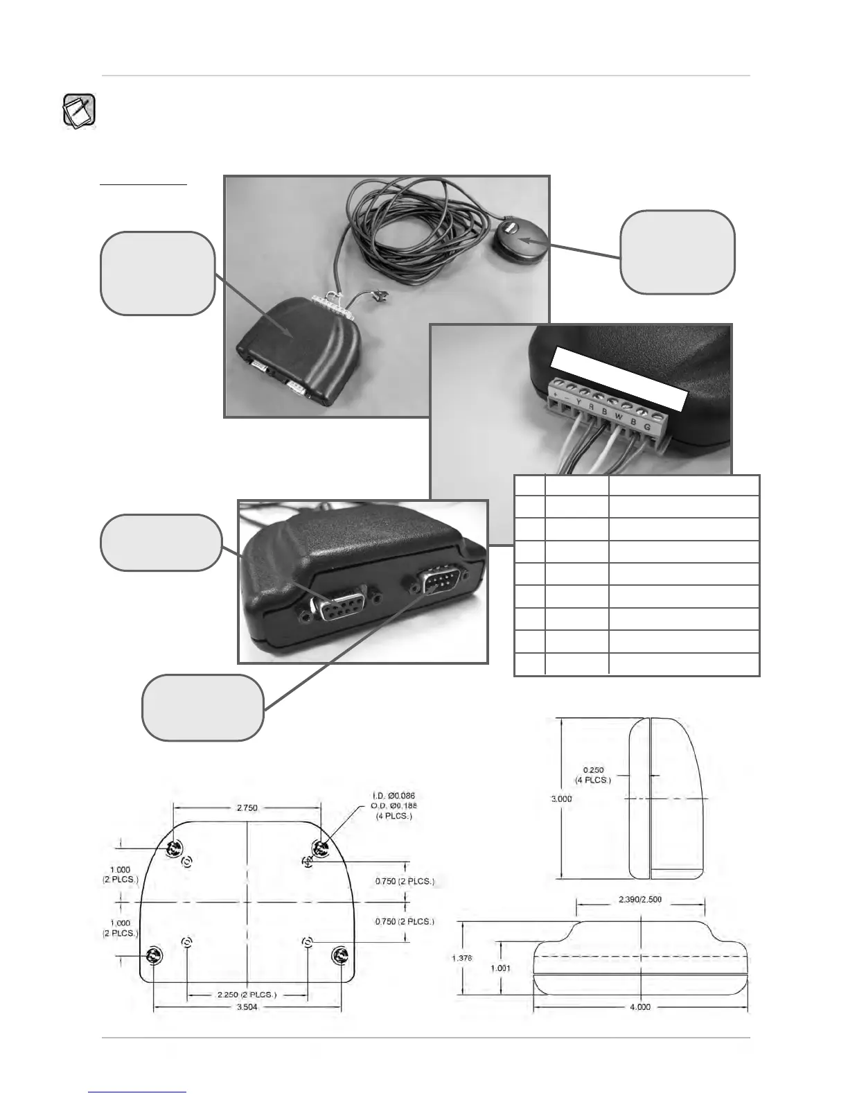
The images below show the GPS adaptor box, included with the HDL-64E, and optional GPS receiver.
[ 12 ]
HDL-64E S2 and S2.1 User’s Manual
GPS EQUIPMENT
GPS Adaptor Box Front & Back View
GPS Adaptor Box
Model No.
HDL-64-ADAPT
(Included)
1 2 3 4 5 6 7 8
# COLOR SIGNAL NAME
1 Red +12V DC Power
2 Black Power Ground
3 Yellow 1 PPS (positive edge only)
4 Red Vin (+5V)
5 Black Ground
6 White Transmit Data
7 Brown Ground (Drain Wire)
8 Green Receive Data
DB-9 M
Connect to Interface
Cable from
HDL-64E Unit
DB-9 F
Connect to Host
Computer Serial Port
GPS Receiver
Model No.
HDL-64-GPS
(Optional)

 Loading...