Do you have a question about the Velodyne HD HDL-64E S2.1 and is the answer not in the manual?
| Type | Lidar Sensor |
|---|---|
| Model | HDL-64E S2.1 |
| Manufacturer | Velodyne |
| Number of Channels | 64 |
| Field of View (Horizontal) | 360° |
| Range | Up to 120 m |
| Accuracy | ±2 cm |
| Power Consumption | 60 W |
| Operating Temperature | -10°C to +60°C |
| Interface | Ethernet |
| Angular Resolution | 0.08° |
| Vertical Resolution | 0.4° |
| Output Rate | 1.3 million points per second |
| Rotational Speed | 5-15 Hz |
| Power Supply | DC |
| Field of View (Vertical) | 26.8° |
Critical safety guidelines and warnings for operating the device.
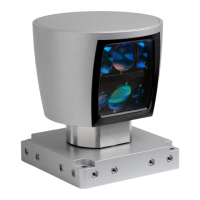
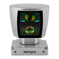
Introduces the HDL-64E S2/S2.1 sensor and compares their features.
Lists all items included in the sensor shipment.
Details the sensor's operational principles, laser system, and data processing.
Instructions for mounting the sensor on its front or back.
Guidance on mounting the sensor from its side.
Instructions for securing the sensor using the top mounting option.
Covers sensor wiring, power, Ethernet, and serial interfaces.
Using the included viewer and developing custom point-cloud applications.
RS-232 commands for controlling spin rate and horizontal FOV.
Configuring sensor IP addresses for communication.
Synchronizing sensor data with GPS time for precise firing.
Explains the format, content, and interpretation of sensor data packets.
Steps to update the sensor's firmware using the provided software.
Detailed drawings of physical dimensions and mounting hole specifications.
Illustrates wiring for power, RS-232, and Ethernet interfaces.
Guides on installing DSR and applying calibration data for accurate visualization.
Instructions for live viewing, recording, and manipulating 3D point cloud data.
Explains keyboard and mouse controls for interacting with the DSR software.
Sample MATLAB code to parse sensor output files and extract calibration data.
MATLAB code snippets for retrieving specific sensor unit parameters.
Detailed explanation of the UDP packet structure, including header, payload, and data fields.
Interpretation of the GPS timestamp and status bytes within the data packet.
Describes the dual point calibration method, including equations and code.
Explains intensity compensation based on focal distance, slope, and distance.
Guidance on using the Ethernet transit timing table for precise data capture analysis.
Visual diagrams showing the physical arrangement of lasers and detectors on the sensor.
Table detailing angular resolution values corresponding to different RPM settings.
Common issues with the sensor and their corresponding resolutions and troubleshooting steps.
Information on obtaining service, maintenance, and contact details for Velodyne.
Comprehensive list of sensor, laser, mechanical, output, and environmental specifications.