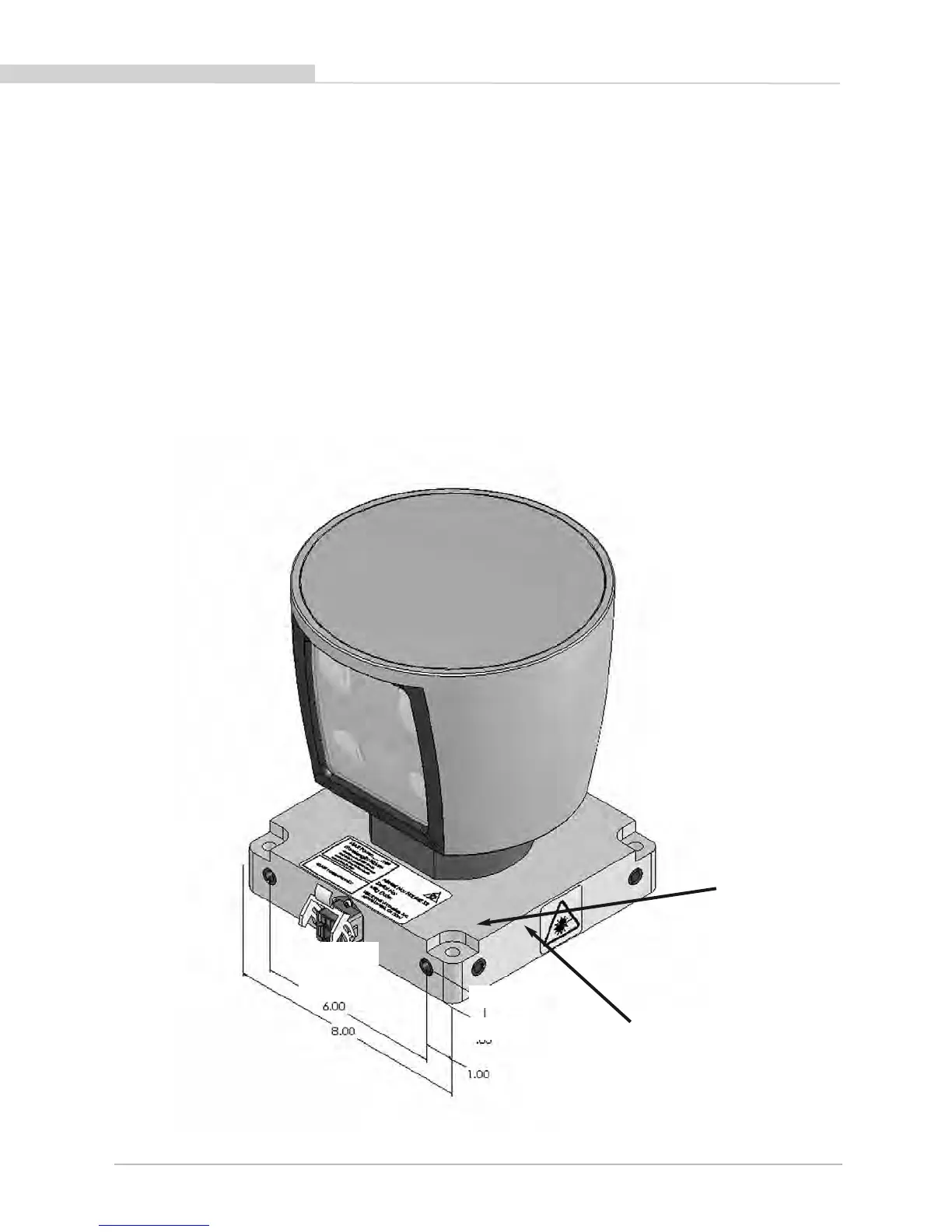
Two M8-1.25mm x
12mm deep mounting
points. (Two per side,
for a total of 8.)
Mounting
Base
[152.4mm]
6.00
[203.2mm]
8.00
[21mm]
.83
[25.4mm]
1.00
The sensor base provides the following mounting options:
• Front/Back mount (Figure 2)
• Side mount (Figure 3)
• Top mount (Figure 4)
The sensor can be mounted at any angle from 0 to 90° with respect to its base. Refer to Appendix A for complete dimensions. For all
mounting options, mount the sensor to withstand vibration and shock without risk of detachment. Although helpful for longer life, the unit
doesn’t need to be shock proofed as it’s designed to withstand standard automotive G-forces.
The sensor is weatherproofed to withstand wind, rain and other adverse weather conditions. The spinning of the sensor helps it shed excess
water from the front window that could hamper performance.
Front/Back Mounting
Figure 2. Front and back HDL mounting illustration.
[ 3 ]
HDL-64E S2 and S2.1 User’s Manual

 Loading...