TECHNICAL MANUAL
15
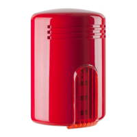
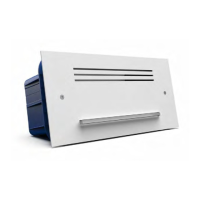
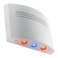
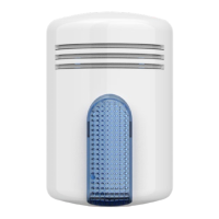
MINI DOGE A / MINI DOGE AL
TERMINAL CONNECTIONS
TERMINAL CONNECTION
1
Trigger (negative = activated) of the LED devoted to the notice of the alarm system
status (alarm system armed/disarmed) - on AL model only
2
Independent command trigger of the LED flashing unit for alarm optical notice
(positive = activated) - see DIP 1, AL model only
3
Sound 1 command (DIP 4 = OFF) - sound 4 command (DIP 4 = ON)
See DIP 2 and DIP 3 settings for trigger selection
3 & 4
Sound 7 command (DIP 4 = OFF) - sound 4 command (DIP 4 = ON)
See DIP 2 and DIP 3 settings for trigger selection
4
Sound 2 command (DIP 4 = OFF) - sound 5 command (DIP 4 = ON)
See DIP 2 and DIP 3 settings for trigger selection
4 & 5
Sound 8 command (DIP 4 = OFF) - sound 5 command (DIP 4 = ON)
See DIP 2 and DIP 3 settings for trigger selection
5
Sound 3 command (DIP 4 = OFF) - sound 6 command (DIP 4 = ON)
See DIP 2 and DIP 3 settings for trigger selection
6
+12 Vdc - Power supply and recharge
7
0 Vdc – Ground
8
Tamper (connect to the tamper line coming from the control panel)
9
Tamper (connect to the tamper line coming from the control panel)
10
Anomaly output. No anomalies = 0 Vdc; anomaly = free
ATTENTION: in case of connection using a missing command, connect all input terminals
to the positive or the negative (see DIP2).
DIP-SWITCHES SETTING
DIP 1 – FLASHING UNIT SELECTION (AL model)
OFF
The flashing unit follows the alarm trigger (default setting)
ON
The flashing unit follows the separated flashing unit trigger - terminal no. 2
DIP 2 – TRIGGER POLARITY SELECTION
OFF Positive trigger (default setting) – terminals no. 3, 4, 5
ON Negative trigger – terminal no. 3, 4, 5
DIP 3 – MISSING / GIVING TRIGGER SELECTION
OFF
Giving trigger – terminals no. 3, 4, 5
ON
Missing trigger (default setting) – terminal no. 3, 4, 5
 Loading...