24
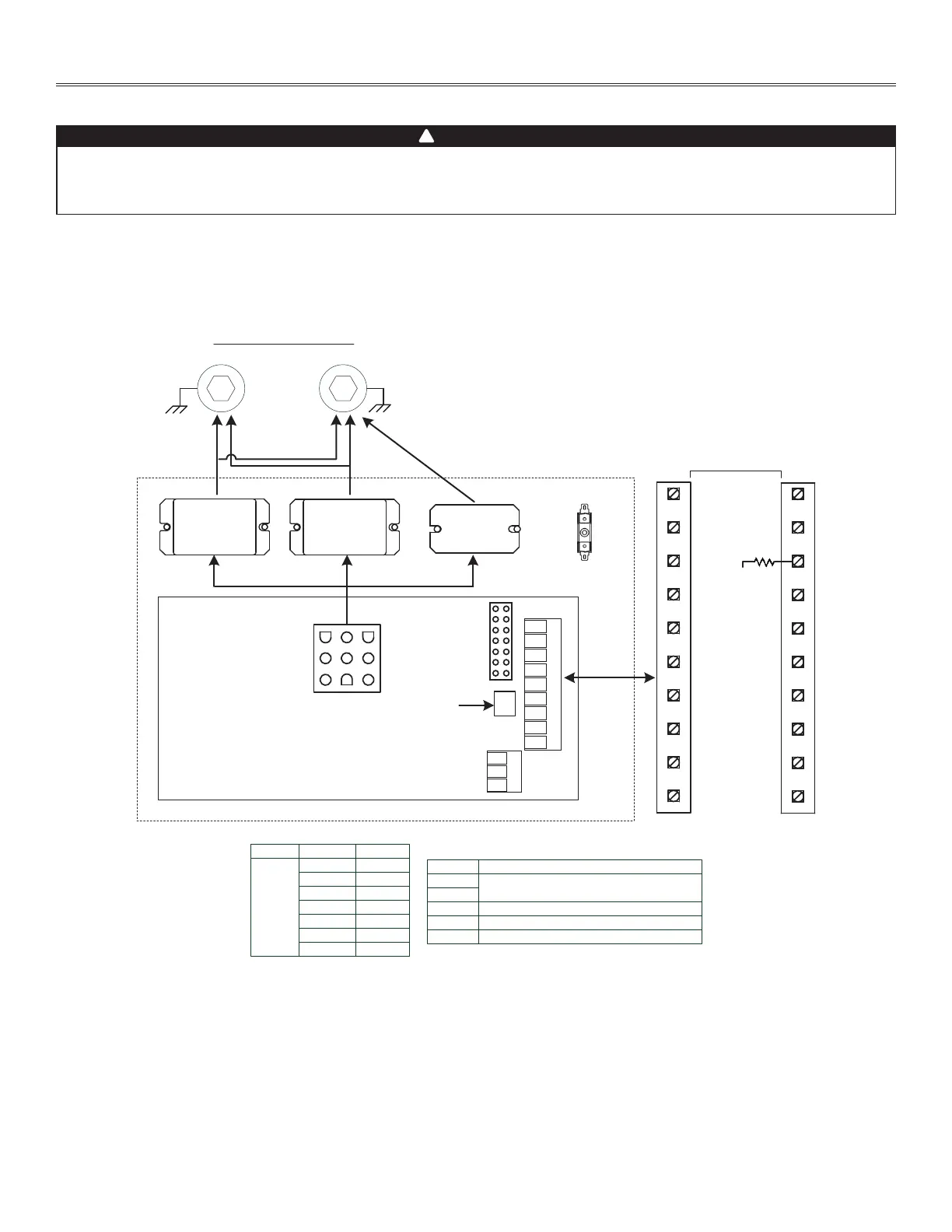
Appendix H
WIRING DIAGRAMS
(Exhaust)
M1
SYSTEM DIAGRAM
Ventilation Fan Motors
M2
(Supply)
J1
J2
J3
J4
JU1
From/To
J3-9
J3-1
J3-8
J3-9
J3-6
J3-7
J3-8
J3-8
J3-2
J3-8
J3-9
Low Speed
Relay
K2
K3
K1
High Speed
Relay
Defrost
Relay
F1
ITEM
DESCRIPTION
K1
Relay DPST 120 VAC, 1 HP, 30 A @ 120 VAC
K2
K3
Relay SPDT 120 VAC, 1 HP, 30 A @ 120 VAC
F1
Fuse 5 A fast acting and fuse holder
UCB1
Electronic Controller
ITEM
C
JU1
OFF
B OFF
A OFF
D ON
E ON
F ON
G ON
POSITION SETTING
10K Defrost
Thermistor
Main Electrical Enclosure
UCB1
6LC, V6LC,12LC & V12LC - Exhaust Defrost - Normal Low Speed
s
top
GREEN
YELLOW
LOW
COM
HIGH
BLACK
RED
OCC.
UNOCC.
REM FAN
INTERLOC
987654321
FF IOCOLYR GB
VE0460A
Ref: 1107006_REV-A
123
456
9 78
3.9K
WARNING
• Risk of electric shocks. Before performing any maintenance or servicing, always disconnect the unit from its power source.
• This product is equipped with an overload protection (fuse). A blown fuse indicates an overload or a short-circuit situation. If
the fuse blows, disconnect the unit from its power source. Discontinue using the unit and contact technical support.
!