27
COM
LOW
MED
HIGH
WH
R
BL
CN2
CN1
WHBK
LINE
NEUTRAL
120 VAC FIELD
WIRING
14 AWG
K1-1
K2-1
TP
M1
(Exhaust)
COM
LOW
MED
HIGH
WH
R
BL
BK/Y
CN3
K1-2
K2-2
TP
K3
J1.2
J1.3
R
R
CN4
K4
J1.4
J1.5
K2
J1.6
K1
R
WH/Y
O
BK
WH
K3
J1.9
BK/R
J1.8
CN5
J1
CN5.3
CN5.4
CN5.5
CN5.2
F1
CN5
F2
K5
K4
K4
CN6
X1
K5
K5
CN5.3
CN5.4
CN5.5
BK/R
WH/R
BK
BK/Y
CN5.2
R
WH
BL
R
O
WH/BL
R
BK
BK/Y
M2
(Supply)
Main Electrical Enclosure Remote Electrical Enclosure (Recirc.)
G/Y
G/Y
G
GND
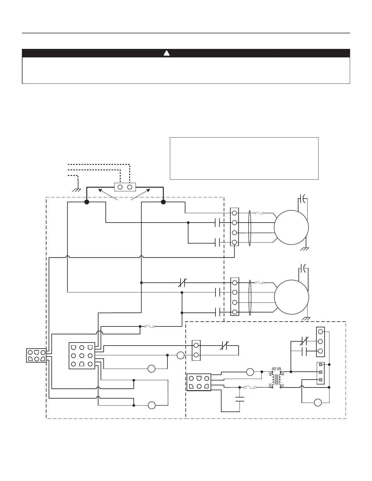
6LC, V6LC,12LC & V12LC - Recirculation Defrost - Normal Low Speed (cont’d)
BK
BK/R
BK/Y
BL
BN
G
G/Y
O
R
WH
WH/BL
WH/R
WH/Y
Y
BLACK
BLACK/RED
BLACK/YELLOW
BLUE
BROWN
GREEN
GREEN/YELLOW
ORANGE
RED
WHITE
WHITE/BLUE
WHITE/RED
WHITE/YELLOW
YELLOW
WIRING COLOR CODE
LOGIC DIAGRAM
BN
BN
BN
BN
Ref: 1107007_REV-A
VE0463A
5
6
4
2
3
1
123
456
9 78
5
6
4
2
3
1
BK
BK
C
R
G
WH
WH
WH
WH
BK
BK
BK
BK
BK
BK
BK
BK
BK/R
WH/R
BK/R
BK/Y
1
2
3
4
1
2
3
4
1
2
1
2
3
2
1
Appendix H (cont’d)
WIRING DIAGRAMS
WARNING
• Risk of electric shocks. Before performing any maintenance or servicing, always disconnect the unit from its power source.
• This product is equipped with an overload protection (fuse). A blown fuse indicates an overload or a short-circuit situation. If
the fuse blows, disconnect the unit from its power source. Discontinue using the unit and contact technical support.
!