28
Appendix H (cont’d)
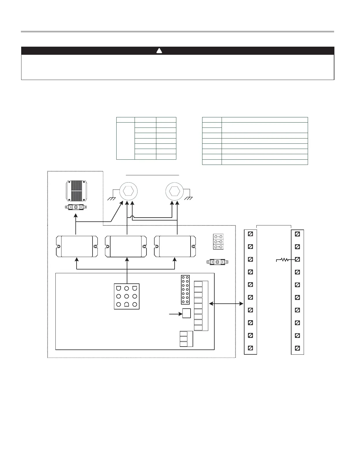
WIRING DIAGRAMS
M1
M2
J1
J2
J3
J4
JU1
K1 K2K3
F1
F2
X1
ITEM
DESCRIPTION
UCB1
TB1
SYSTEM DIAGRAM
7000 - Recirculation Defrost
Relay DPST 120 VAC, 1 HP, 30 A @ 120 VAC
Relay DPDT 24 VAC, 1/2 HP, 15 A @ 120 VAC
Fuse
5 A fast acting and fuse holder
Fuse 0.5 A fast acting and fuse holder
24 VAC Transformer 40 VA
Electronic Controller
ITEM
C
JU1
OFF
B OFF
A ON
D ON
E ON
F ON
G ON
POSITION SETTING
Line Voltage Terminal Block (120 VAC)
K1
K2
K3
TB1
F1
F2
X1
UCB1
(Exhaust)
Ventilation Fan Motors
(Supply)
stop
High Speed
Relay
Low Speed
Relay
Recirculation
Relay
10K Defrost
Thermistor
987654321
FF IOCOLYR GB
123
456
9 78
Main Electrical
Enclosure
Ref: 1107008_REV-A
From/To
J3-9
J3-1
J3-8
J3-9
J3-6
J3-7
J3-8
J3-8
J3-2
J3-8
J3-9
GREEN
YELLOW
LOW
COM
HIGH
BLACK
RED
OCC.
UNOCC.
REM FAN
INTERLOC
3.9K
VE0464A
WARNING
• Risk of electric shocks. Before performing any maintenance or servicing, always disconnect the unit from its power source.
• This product is equipped with an overload protection (fuse). A blown fuse indicates an overload or a short-circuit situation. If
the fuse blows, disconnect the unit from its power source. Discontinue using the unit and contact technical support.
!