Installaon and electrical connecon
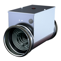
Electrical duct heaters EKA can be installed horizontally in any posion except electrical connecon box
downward and vercally (only if the air flow direcon upwards) (see Fig. 2).
IMPORTANT:
The installaon to the mains power supply may only be wired by a competent electrician. The power
supply cable must be selected in the rao with power of the heater. When installing these heaters, the
standards and regulaons in force in your country must be followed strictly adhered to. Within the installaon
an electrical isolaon automac circuit breaker (not included) must be present, to enable the installer to cut all
power supply lines. Automac circuit breaker must be selected regarding power and nominal current (see the
electrical rang plate on the lid of heater) of the heater and should have characterisc B. Connect the heater to
the mains power supply, check that the voltage, frequency, power and current are the same as those indicated
on the electrical rang plate. The heater must be earthed.
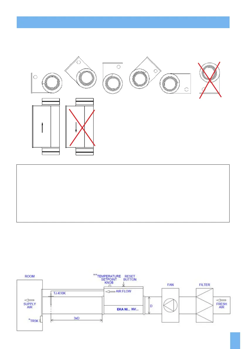
We recommend install supply air temperature sensor in distance mulplied by the heater's diameter (3xD).
For example: heater EKA diameter 200 mm, sensor's installaon distance will be: 3x200=600 mm.
Fig. 3. Mounng example EKA NV/NI…
*- TR5K is used in EKA NI heater version.
**- Temperature set point knob is used in EKA NV heater version.
Fig. 2
Fig. 3
5