* – other setpoint range on request
** – power of the heater (kW)
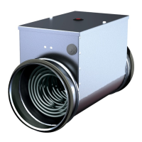
Electrical duct heaters EKA NV … are designed with integrated temperature control, one
temperature sensor, potentiometer on the top of the heater casing for temperature setpoint.
When the heater power supply is switched on, LED 6 on the controller (EKR-KN…) PCB (see Fig.
11) flashes once every 8 seconds if setpoint is 0 °C and every second if setpoint is higher than 0 °C. If
controller turns on the heating depending on the demand, LED 5 lights (see Fig. 11).
Heaters EKA NV … operates by the supply (TJ-K10K) air temperature sensor. Setpoint
temperature (0…30) °C.
There can be set the different desired (setpoint) air temperature by potentiometer on the top
of the heater casing.
If LED 6 lights continuously it means that there is a failure of: supply (TJ-K10K) air temperature
sensor or potentiometer on the top of the heater casing.
IMPORTANT: If failure appears, power supply must be switched off and only then performed
fault elimination works.
Electrical duct heaters EKA NI … are designed with integrated temperature control, one
temperature sensor, wired remote control panel (TR5K) for temperature setpoint.
When the heater power supply is switched on, LED 6 on the controller (EKR-KN…) PCB (see Fig.
11) flashes once every 8 seconds if setpoint is 0 °C and every second if setpoint is higher than 0 °C. If
controller turns on the heating depending on the demand, LED 5 lights (see Fig. 11).
Heaters EKA NI … operates by the supply (TJ-K10K) air temperature sensor. Setpoint
temperature (0…30) °C.
There can be set the different desired (setpoint) air temperature by wired remote control panel.
If LED 6 lights continuously it means that there is a failure of: supply (TJ-K10K) air temperature
sensor or wired remote control panel TR5K.