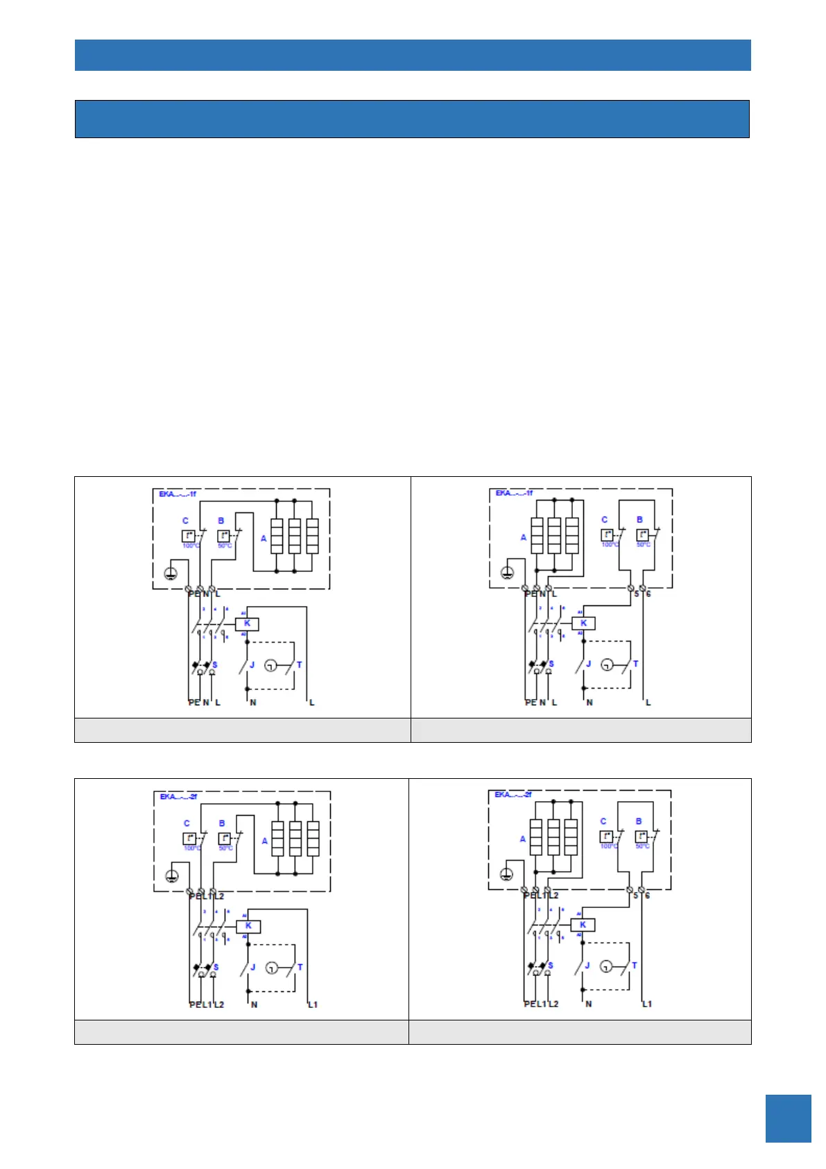
S – Automatic circuit breaker
J – Switch
T – Timer
EKR-KN… – PCB of temperature controller
V1, V2 – Triacs
A – Heating elements
B – Overheat thermostat with automatic reset
C – Overheat thermostat with manual reset
K – Contactor (relay)
PTC – Sensor for minimum air velocity detection
PS – Differential pressure switch for air flow detection
TJ-K10K – Supply air temperature sensor
TR NTC10 – Room temperature sensor panel
TR5K NTC10 – Room temperature sensor panel with remote setpoint knob
TR5K – External remote setpoint knob panel