24
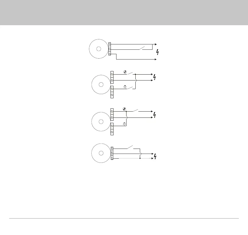
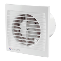
Wiring diagram for a fan equipped with a timer/timer and a humidity sensor, without a built-in switch.
LT (ST)
L(~)
SN (~)
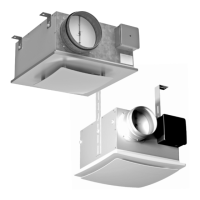
Wiring diagram of the Xstar fan with separate switching on of the fan and the built-in lamp.
S1
N(~)
S2
L(~)
L(~)
Wiring diagram of the Xstar fan with the simultaneous switching on of the fan and the integrated lamp.
S
N(~)
L(~)
L(~)
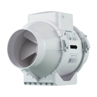
Wiring diagram of the P and P1 fan equipped with a timer/timer and a humidity sensor.
S (ST)L
L(~)
S
N(~)
Terminal designations on wiring diagrams:
L – line S1 – external fan switch
N – neutral S2 – external lamp switch
S – external switch