Vantage 5000 1.0v-11.2016 5 | Page
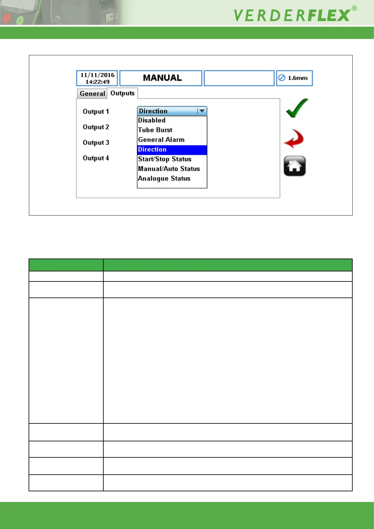
By touching the down arrow of each output a selection submenu appears, as shown below:
The functionality of each submenu element is shown in the table below where logic 0 refers to 0V and logic 1 refers to the I/O
positive power supply voltage, which would nominally be 24V. Note that in order to observe this voltage change a 10K Ω pull
up resistor should be used between the selected output pin and the remote 24V (pin 10).
Figure 6 Selected Output Submenu
Functionality status Description
Disabled The selected output pin is not allocated and will default to a logic 1 level.
Tube burst
The selected output pin will be a logic 1 when no burst is detected and a logic 0 when uid is
detected for the burst sensor.
General Alarm
The selected output pin will be a logic 1 when there are no faults on the pump and a logic 0 when
any of the following events occur:
• Door open
• Tube Burst
• Motor Stalled
• Power failure
• Over temperature
• Source Empty
(1
• Destination Full
(1
• Empty Bund
(1
• Communication failure
(2
• Missing 4-20 mA
(3
(1
Pump must be congured for 25 WAY Remote I/O Connector.
(2
Fieldbus pump versions only.
(3
4-20mA must be enabled.
Direction
The selected output pin will be a logic 1 when the pump is set to run in a clockwise direction and
a logic 0 when the pump is set to run in an counter-clockwise direction.
Start/Stop Status
The selected output pin will be a logic 1 when the pump is not running and a logic 0 when the
pump is running.
Manual/Auto Status
The selected output pin will be a logic 1 when the Manual/Auto, pin 1 of the 25 WAY Remote I/O
Connector, is not connected and a logic 0 when the pin is connected to 0V
Analogue Status
The selected output pin will be a logic 1 when the pump is in Human Machine Interface (HMI)
mode and will be set to a logic 0 when set for 4-20mA, 0–10V or proportional ow