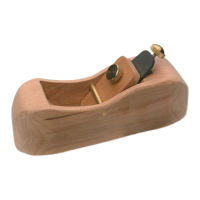
This document describes the Veritas Wooden Plane Hardware Kit, designed for crafting a basic bevel-down, wood-bodied smooth plane with a Norris-style adjuster. The kit provides the essential hardware components, allowing the user to create the plane body and lever cap from their preferred hardwood.
Function Description
The Veritas Wooden Plane Hardware Kit enables the construction of a custom-made wooden plane. Unlike traditional planes that rely on a hard-to-adjust wedge, this design incorporates a Norris-style adjuster for precise blade control. The blade is secured by a user-made wooden lever cap, which is clamped by a brass knob, providing the necessary clamping force. A brass cross pin retains the lever cap. The kit focuses on providing the mechanical components, leaving the aesthetic and ergonomic design of the plane body and lever cap to the user's preference, as long as the specifications for fitting the components are met.
Important Technical Specifications
The kit includes the following hardware components:
- Adjustment Cup: 1 unit
- Wood Screw, #10 x 3/4": 1 unit, used to secure the adjustment cup.
- Adjustment Mechanism: 1 unit, a Norris-style adjuster for blade depth and lateral adjustment.
- 1/4-20 Brass Insert: 1 unit, for the lever cap knob.
- Blade, 1 5/8": 1 unit (packaged separately). This blade comes with a 23° primary bevel and a finely ground 25° micro-bevel, designed for strong, long-wearing edge retention.
- Lever Cap Knob: 1 unit, a brass knob for clamping the lever cap.
- Brass Cross Pin: 1 unit, for retaining the lever cap.
The required material for the plane body and lever cap is dense, close-grained hardwood. Beech and hard maple are recommended, but cherry and walnut are also suitable.
Dimensions for the plane body:
- Initial hardwood blank size: 8"L x 2 1/4"W x 2 1/2"H.
- Inner body width: 1 11/16".
- Side pieces thickness: Approximately 5/16".
- Mouth location: 3" from one end of the bottom of the inner body.
- Blade bed location: 45° from the 3" mark.
- Escapement radius: Approximately 4".
- Blade bed layout marks: 2 1/2" and 3 5/16" up from the bed lip along the center line.
- Adjustment cup hole: 7/8" diameter, 21/32" deep, at the 3 5/16" mark.
- Pilot hole for wood screw: 1/8" diameter, 1/2" deep, inside the 7/8" hole.
- Adjuster pocket hole: 7/8" diameter, 3/8" deep, at the 2 1/2" mark.
- Cross-pin hole: 1/4" diameter, located 5/8" back from the blade bed edge and 1 1/2" up from the sole.
Dimensions for the lever cap:
- Hardwood piece size: 3/8" x 1 5/8" x 3 1/2".
- Hole for brass insert: 3/8" diameter, located at 2 15/16" along the center line.
- Bevel: 30° on one edge, 1/16" from the top edge.
Optional Accessory Blades (0.125" x 1 5/8"):
- 05P22.02: 25° A2 Tool Steel Blade
- 05P22.52: 25° O1 Tool Steel Blade
- 05P22.72: 25° PM-V11® Tool Steel Blade
Usage Features
The kit is designed for users with basic woodworking skills. The instructions guide the user through the process of preparing the body, drilling holes for the adjuster, assembling the body, shaping the body, and making the lever cap.
Key steps in usage:
- Material Selection: Choose a dense, close-grained hardwood for the plane body and lever cap.
- Body Preparation: Cut the hardwood blank to size, mark and cut the inner body, and lay out the mouth, blade bed, and escapement.
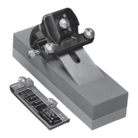
- Drilling for Adjuster: Precisely drill holes for the adjustment cup and mechanism using a drill press and a 45° jig block (which can be made from waste material).
- Body Assembly: Glue the inner body cut-outs and side pieces, ensuring a tight mouth opening. The blade is used temporarily during this step to position the front piece.
- Cross Pin Installation: Drill a 1/4" diameter hole for the brass cross pin, using a jig block to prevent tear-out.
- Body Shaping: Sketch and cut the desired shape and profile for the plane body using a bandsaw, then refine with rasps and sandpaper for ergonomic comfort.
- Lever Cap Creation: Cut and shape the lever cap from hardwood, drill a hole for the brass insert, and bevel one edge.
- Final Assembly: Insert the brass cross pin, install the adjustment cup with the wood screw, place the adjustment mechanism, position the blade, push the brass insert into the lever cap (optionally with epoxy), slide the lever cap under the cross pin, and attach the lever cap knob.
- Finishing: Sand and finish the plane as desired.
Maintenance Features
The primary maintenance feature relates to the blade. The supplied blade has a 23° primary bevel and a 25° micro-bevel, designed for durability. It can be honed many times before the primary bevel needs to be reground. Additional honing is recommended to improve performance. The instructions emphasize the importance of careful handling due to the blade's sharpness to prevent serious injury. The brass insert for the lever cap knob can optionally be secured with epoxy to hold it in place. The lever cap may require sanding on its top surface to ensure it fits easily under the cross pin.