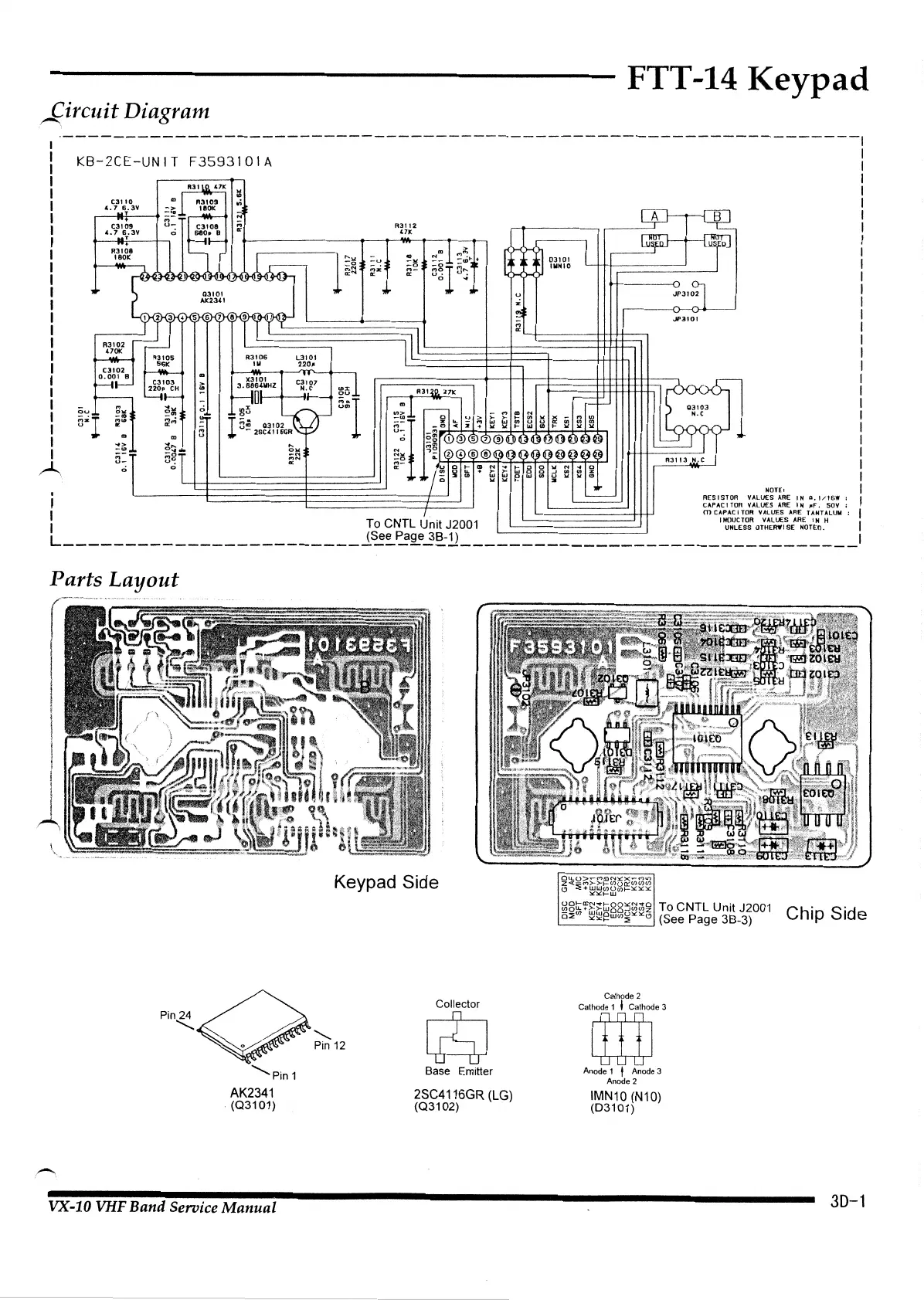
FTT-14 Keypad
~ircuit
Diagram
A
----------------------------------------------------------------1
KB-2CE-UNIT F3593101A
I
I
I
I
I
I
I
I
I
I
I
I
I
I
I
I
I
I
I
I
I
I
I
ou
5"l
CJI
10
4.
7
6.3V
T
r
~
..
-a
-
..
~
..
"'"'
au
U<n
;;;.I
-u
~z
~
RJI
12
47K
~~
>
"'1~~
§~r§~H·
0 "
-1
.
I"'
~
I
o!!~~rCD@®0®GJ>00~00@@1
I
L_J
l f l
,.
I
a~rl
~~!j
~~
~~
'l~l
<V~~®@~~H~~~~@~~B~
R3113
H.C
II
0
0
~
-jluloil,_.,,.._,t;oo""'"~l
~~~~·e9~~~~t2~~
1
HOTEl I
- RESISTOR VALVES
ARE
IN
ll.l/t6W
I I
CAPAC I
TOR
VALVES
ARE
IN
11F.
SOV ;
1
J..
. m
c7~~~;g~
v~~~C:s
A=~E
T~=T~LUM
: 1
1 To CNTL Untt J2001
uNLEss
oTHERWisE
NoTEo.
1
L------------------------1~~~~2~~--------------------------------l
Parts
Layout
I
I
l
I
l
I
A
Keypad Side
Collector
Pin24Q"
"""
Pin
12
0
~
-
"Pin
1
AK2341
(Q31
01)
VX-10 VHF Band Service
Manual
Base Emitter
2SC4116GR
(LG)
(Q31
02)
OU.O>'-'Ma:lN:OCX....-r'Ho
a<(~7~ru0~~~~;2~
::S:::~t-w
001-a:lN'Iti-QQ~N"'<tQ
(/)QU.+>->-woo...J(/)(J)z
o~oo
~~~ww~~x:(j
To CNTL Unit J2001
(See Page 3B-3)
Calhode 2
Cathode 1 I Cathode 3
m
Anode 1 J Anode 3
Anode 2
IMN10
(N10)
(03101)
Chip Side
30-1
 Loading...