The provided document is an installation manual for the Vertiv NetSure™ 7100 Series -48 VDC Power System. This system is designed to provide -48 VDC power, likely for telecommunication facilities or similar applications requiring reliable DC power.
Function Description
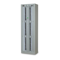
The NetSure™ 7100 Series is a -48 VDC power system that integrates rectifiers, converters, and battery management to ensure continuous and stable power delivery. It is designed to be installed in a relay rack and can be configured with various distribution panels for different load requirements. The system supports both single and dual voltage distribution panels, including -48 VDC, +24 VDC, and -58 VDC outputs, depending on the specific configuration.
The core function of the system is to convert incoming AC power (Nominal 208 VAC / 240 VAC, Single Phase, 50 Hz / 60 Hz) into stable -48 VDC power. It also supports battery backup to maintain power during AC outages. The system's controller (NCU Controller 1M830DNA) manages and monitors all aspects of the power system, including rectifiers, converters, battery charging, and alarms.
Key components and their functions include:
- Rectifier and Converter Modules: These modules perform the AC-to-DC conversion and DC-to-DC conversion (for +24VDC or -58VDC outputs). They are hot-swappable, allowing for replacement or installation without system shutdown.
- Battery Trays: The system can be furnished with battery trays for housing backup batteries. These trays include battery disconnect circuit breakers for safety and isolation.
- Distribution Panels: Various distribution panels are available to connect different types of loads, including single voltage (-48 VDC) and dual voltage (-48 VDC / +24 VDC or -48 VDC / -58 VDC) options. These panels accommodate bullet/TPS/TLS circuit breakers or fuses and GMT distribution fuse blocks.
- System Interface Board (562662): This board provides connections for battery tray fuse alarms, battery rack fuse alarms, system voltage monitoring test points, and temperature probes. It also includes an NCU CAN Port for communication with other devices.
- IB2 Controller Interface Board (MA4C5U31): This optional board offers programmable relay outputs, digital inputs, and additional temperature probe connections. It supports an ESTOP function for emergency shutdown.
- Optional EIB (Controller Extended Interface Board) (MA455U41): This board extends the system's capabilities with additional current inputs (for shunts), voltage inputs (for battery block and midpoint monitoring), programmable relay outputs, and temperature probes.
- IB4 (2nd Ethernet Port Board) (558076): Provides an additional Ethernet port for network connectivity.
- NCU Controller (1M830DNA): The central control unit for monitoring and managing the power system. It features a local display with navigation keys and indicators for status and alarms. It also supports remote monitoring via an Ethernet connection (Web Interface).
The system is designed for installation in telecommunication facilities (CO, vault, hut, or other environmentally controlled electronic equipment enclosures) and is suitable for connection to a Common Bonding Network (CBN).
Important Technical Specifications
- Input Voltage: Nominal 208 VAC / 240 VAC, Single Phase, 50 Hz / 60 Hz.
- Output Voltage: -48 VDC (main output), with optional +24 VDC or -58 VDC outputs via converters.
- Rectifier Current Limit: Configurable via the NCU controller.
- Overcurrent Protection: AC input branch circuit protective devices should be time-delay or high inrush type, with a maximum overcurrent protection device of 30 A.
- Wire Sizes: Recommended 10 AWG copper wire (THHN 90°C) for AC input, based on NEC Table 310.15 (B) (16) for 40°C ambient temperature. Equipment grounding conductors are also specified.
- Conduit Size: 3/4" for AC input.
- Torque Specifications:
- Battery tray cables to system busbars: 75 in-lbs (1/4-20 bolts).
- Lug adapter busbars: 72 in-lbs (1/4" bolts).
- Load lug hardware: 300 in-lbs (3/8" bolts).
- SPD earth ground connection: 72 in-lbs (1/4-20 hardware).
- Relay rack grounding connection: 84 in-lbs (1/4-inch hardware).
- Programmable relay outputs and digital inputs on IB2/EIB: 2.2 in-lbs.
- Battery connections to distribution cabinet busbars: 300 in-lbs (3/8-inch hardware with standard flat and lock washer), 180 in-lbs (3/8-inch hardware with Belleville lock washer).
- GMT distribution fuse block: 4.5 in-lbs (26-14 AWG wire).
- System Interface Board TB1: 0.28Nm or 2.48 in-lb (14AWG to 30AWG wire).
- Battery Capacity: Configurable in the NCU controller.
- Relay Ratings (IB2/EIB):
- Steady State: 0.5 A @ 60V DC; 1.0 A @ 30V DC.
- Peak: 3 A @ 30V DC.
- Digital Input Ratings (IB2):
- Maximum Voltage: 60 VDC.
- Active High: > 19 VDC.
- Active Low: < 1 VDC.
- Module Mounting: Rectifier and converter modules are hot-swappable. Converter modules have specific mounting positions (far right, lower three module mounting assemblies).
- Ethernet Connectivity: NCU front panel (10/100M Ethernet, RJ-45) for local connection, IB4 board (10M Ethernet, RJ-45) for LAN connection. Default IP address: 192.168.1.2.
- CAN Bus: NCU CAN Port (RJ-45) for connecting supporting devices like SM-Temp Modules.
Usage Features
- Modular Design: Rectifier and converter modules are hot-swappable, allowing for easy expansion, maintenance, and replacement without interrupting power.
- Flexible Distribution: Supports various load distribution panels, including single and dual voltage options, to meet diverse application requirements.
- Battery Backup: Integrates with battery trays and disconnect circuit breakers for reliable backup power during AC failures.
- Comprehensive Monitoring and Control: The NCU controller provides extensive monitoring of system parameters (voltages, currents, temperatures, alarms) and allows for configuration of various settings (e.g., float voltage, equalize voltage, battery current limit, temperature compensation).
- Local and Remote Access: The NCU controller features a local display with navigation keys for direct interaction and a Web Interface for remote monitoring and configuration via Ethernet.
- Alarm Management: Provides programmable relay outputs for alarms (dry Form-C contacts) and digital inputs for external alarm signals. The "Critical Summary" alarm operates in a "Fail Safe Mode."
- Temperature Monitoring: Supports multiple temperature probes for monitoring battery and system temperatures, with configurable alarm thresholds.
- Battery Block and Midpoint Monitoring (Optional EIB): Enhanced battery monitoring capabilities to detect abnormal block voltages or midpoint voltages within battery strings.
- ESTOP Function: Emergency shutdown capability via a digital input on the IB2 board, which shuts down rectifiers/converters and opens LVD contactors.
- Generator Input Support: Optional kit (P/N 564219) for connecting an external generator to feed the rectifier output bus.
Maintenance Features
- Hot-Swappable Modules: Rectifiers and converters can be inserted or removed while the system is operating, simplifying maintenance and upgrades.
- Diagnostic Indicators: The NCU controller and individual modules have LED indicators for quick visual status checks (Status, Minor Alarm, Critical/Major Alarm, Power, Protection, Alarm).
- Configuration Backup: Controller configuration settings can be saved to a USB drive, allowing for easy restoration if needed. A configuration drawing (C-drawing) and configuration files are provided with the system.
- Alarm History: The NCU controller stores active alarms and alarm history for troubleshooting.
- Self-Test Functions: The NCU controller includes an alarm relay test feature to verify external alarm relays.
- Easy Access: The distribution cabinet's front door can be opened for access to internal components, and covers for AC input connectors are removable.
- Clear Wiring Diagrams: The manual provides detailed wiring diagrams for battery trays, distribution panels, and circuit card connections, aiding in installation and troubleshooting.
- Recommended Torques: Specific torque values are provided for various connections to ensure proper and secure installation, reducing the risk of loose connections and potential failures.
- Technical Support Site: Vertiv provides an online support portal for additional assistance with installation or operational issues.