REV : 0
REV DATE : 1/19
DPN004903
Page :1 /1
Form No.: DPN001040_REV4
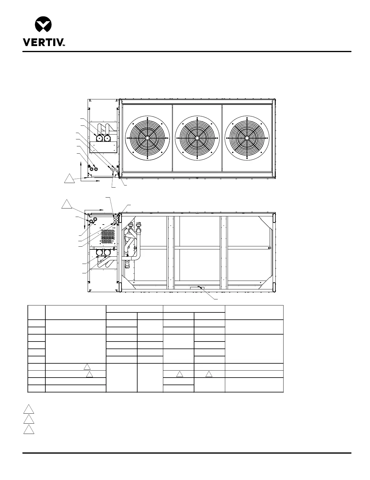
PRIMARY CONNECTION LOCATIONS
LIEBERT CW
CW305, 375, 415 W/ BOTTOM DISCHARGE
FRONT LEFT FACING ELECTRICAL/PIPING COMPARTMENT
HV1
HV2
LV1
LV3
LV2
HV1
HV2
LV4
LV2
LV3
X
Y
O
1
O
X
Y
1
LV4
LV1
CD
Top View
Bottom View
R
S
X in. (mm) Y in. (mm) X in. (mm) Y in. (mm)
HV1 2-7/8 (73) 2-1/2 64) 5 (127)
HV2 6-1/4 (159) 5-5/8 (143) 3-1/4 (83)
LV1 18-1/8 (459) 6-3/8 (163) 5-1/2 (140)
LV2 19-1/2 (494 5 (129 3-1/2 (89)
LV3 20-7/8 (529) 6-3/8 (163) 5-1/2 (140)
LV4 22-1/4 (564) 5 (129) 3-1/2 (89)
CD Condensate Drain 84-5/8 (2149) 54-1/2 (1384) 3/4" NPT Female
CP Condensate Pump 1/2" O.D. Cu
S Supply Pipe Connection 15 (381)
R Return Pipe Connection 9 (229)
20-5/8 (524)
22-5/8 (575)
Electrical Conn. (Low Volt) 1-1/2"
N/A N/A
28-3/4 (731) 4-1/8" O.D. Cu
POINT Description
Electrical Conn. (High Volt)
Connection Size/Opening
2-1/2"6-1/4 (160)
Notes:
1. Drawing not to scale. All dimensions from right corner on service side and have a tolerance of ± 1/2" (13mm).
2. Condensate Pump to be field located and installed by customer.
3. Field pitch Condensate Drain line a minimum of 1/8" (3.2mm) per 12" (305mm).
Install an external 5-1/2" (140mm) trap in the drain line (if desired). The factory unit does not contain a trap. Select appropriate drain system materials.
The drain must comply with all local codes.
4. Piping connection can be made at the top or bottom of the unit.
2
2 2
3
S
R