REV : 0
REV DATE : 1/19
DPN004901
Page :1 /1
Form No.: DPN001040_REV4
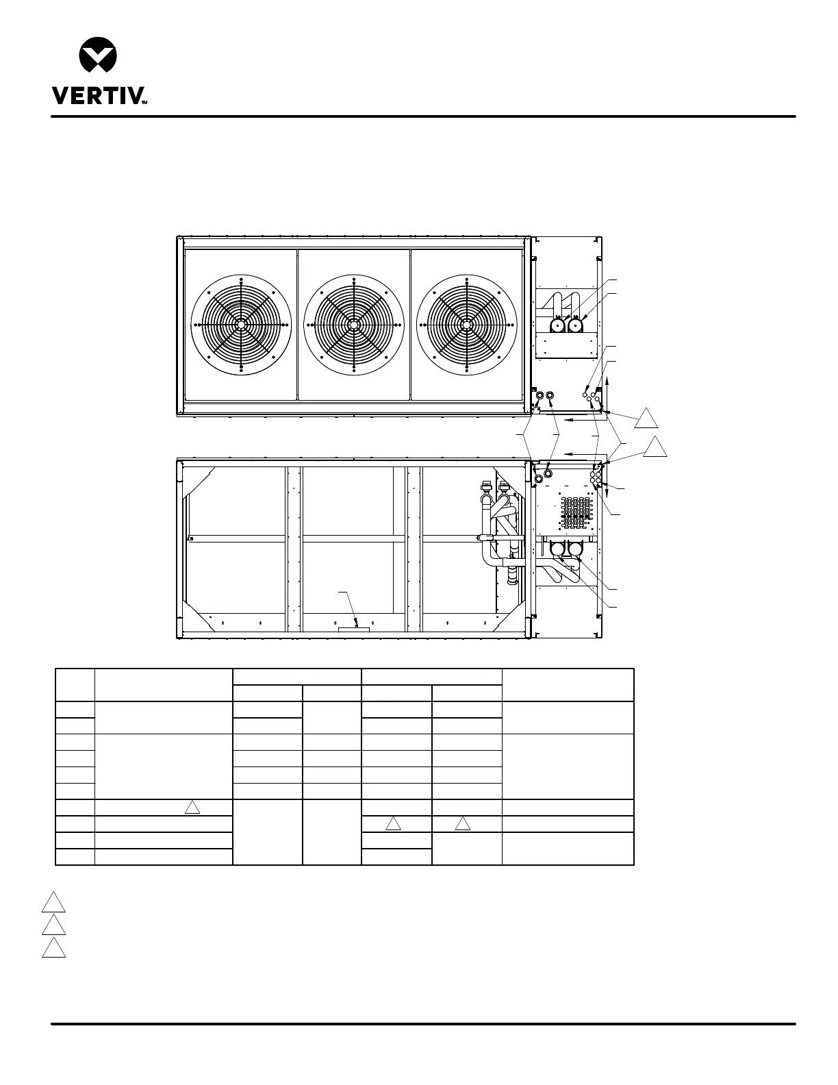
PRIMARY CONNECTION LOCATIONS
LIEBERT CW
CW305, 375, 415 W/ BOTTOM DISCHARGE
FRONT RIGHT FACING ELECTRICAL/PIPING COMPARTMENT
X in. (mm) Y in. (mm) X in. (mm) Y in. (mm)
HV1 21 (533) 21-3/8 (543) 5 (127)
HV2 17-5/8 (448) 18-1/4 (464) 3-1/4 (83)
LV1 5-3/4 (148) 6-3/8 (162) 3-1/4 (83) 5-1/2 (140)
LV2 4-38 (113) 5 (127) 1-1/4 (32) 3-1/2 (89)
LV3 3 (78) 6-3/8 (162) 3-1/4 (83) 5-1/2 (140)
LV4 1-5/8 (43) 5 (127) 1-1/4 (32) 3-1/2 (89)
CD Condensate Drain 83 (2108) 54-1/2 (1384) 3/4" NPT Female
CP Condensate Pump 1/2" O.D. Cu
S Supply Pipe Connection 15 (381)
R Return Pipe Connection 9 (229)
Electrical Conn. (Low Volt) 1-1/2"
POINT Description
Electrical Conn. (High Volt)
Connection Size/Opening
2-1/2"
28-3/4 (731)
6-1/4 (159)
4-1/8 O.D. Cu
N/A N/A
Notes:
1. Drawing not to scale. All dimensions from right corner on service side and have a tolerance of ± 1/2" (13mm).
2. Condensate Pump to be field located and installed by customer.
3. Field pitch Condensate Drain line a minimum of 1/8" (3.2mm) per 12" (305mm).
Install an external 5-1/2" (140mm) trap in the drain line (if desired). The factory unit does not contain a trap. Select appropriate drain system materials.
The drain must comply with all local codes.
4. Piping connection can be made at the top or bottom of the unit.
HV1
HV2
LV1
LV3
LV2
LV1
X
Y
O 1
O
X
Y
1
LV4
LV3
CD
Top View
Bottom View
S
R
22
3
R
S