Vertiv | Liebert
®
ITA2
™
, 8-10kVA, 208/220V Three-Phase UPS Quick-Start Guide | Rev. 0 | 01/18 | 1
LIEBERT
®
ITA2™ UPS
Quick-Start Guide—60Hz, 208V, 8-10kVA
The complete Liebert ITA2 UP user manual is available at Vertiv’s Web site,
www.vertivco.com/en-us/products-catalog/critical-power/uninterruptible-power-
supplies-ups/ or by using the QR code at right.
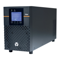
Unpacking and Inspection
Unpack and inspect the UPS and its accessories,
shown at right
1. If any problem is found, file a damage claim with the
carrier immediately and send a copy to Vertiv at:
Vertiv
1050 Dearborn Drive
P.O. Box 29186
Columbus, Ohio 43085 USA
2. Check the accessories and models against th
e
de
livery list. If any problem is found, notify your local
Vertiv representative immediately.
Single-Input Configuration
1. Remove the conduit box cover to gain access to the
input
and output terminal blocks.
2. Remove the knockout plates and attach
the
condui
ts to the rear of the conduit box.
Hardwire Connections—UPS Input
3. Leave the shorting busbars in place on the UPS
input t
erminal block.
4. Using Figure 1, make these connections:
• Phase A cable from the upstream feeder
panel
to UPS
Jumper 11
• Phase B cable from the upstream
feeder panel
to UPS
Jumper 12
• Phase C from
the upstream feeder panel to
UPS Te
rminal 13
• Neutral fr
om the upstream feeder panel to UPS
Terminal
14 or 15
• The safety equipment ground cable fr
om
upst
ream feeder panel to UPS ground stud 10
Hardwire Connections—UPS Output
The UPS has two output terminal block sections, one is always on and the other is programmable/controllable.
These instructions will list the always-on connections first, followed by the programmable connections inside
parentheses.
1. Using Figure 1, make these connections:
• Phase A cable from UPS Terminal 4 (9) to the downstream distribution panel Phase A on the panelboard main breaker
• Phase B cable from UPS Terminal 3 (8) to the downstream distribution panel Phase B on the panelboard main breaker
• Phase C cable from UPS terminal 2 (7) to the downstream distribution panel Phase C on the panelboard main breaker
• Neutral cable from UPS terminal 5 (6) to the downstream distribution panel neutral bus
• The safety equipment ground cable from UPS Ground Stud 1 to the downstream distribution panel ground bus
2. Replace the conduit box cover and secure it.
Corner
Braces
Protective
Packing
Protective
Packing
Bag of
Hardware
Front
Panel
Liebert ITA2
Support
Base
Liebert ITA2 and Accessories as Shipped