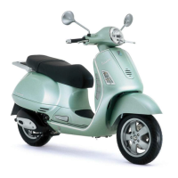
This document is a service station manual for the Vespa GTV 250 i.e., providing comprehensive information for maintenance and repair operations. It is intended for use by workshops of Piaggio-Gilera dealers and assumes a basic understanding of mechanical principles and repair techniques.
The manual begins with a pre-delivery section, outlining essential checks and tests to be performed before vehicle handover. These include aesthetic inspections (paintwork, plastic fitting, scratches, dirt), tightening torque inspections (safety locks, various fixing screws for shock absorbers, wheels, brakes, engine, handlebar, and steering), and electrical system checks (main switch, lights, brake lights, turn indicators, instrument lighting, horn, electric starter, engine stop switch, and electric saddle opening button). Important cautions regarding battery charging, installation, electrolyte handling, and fuse usage are provided. Level checks for hydraulic brake fluid, rear hub oil, engine coolant, and engine oil are also specified. A road test section details checks for cold start, instrument operations, throttle response, stability, and suspension efficiency. Finally, a static test after the road test covers hot engine restart, minimum seal, steering rotation, possible leaks, and radiator fan operation. Tyre pressure checks and adjustments are also highlighted.
Technical Data
The technical data section provides detailed specifications for the Vespa GTV 250 i.e.
- Vehicle Identification: Chassis prefix and engine prefix are provided for identification.
- Engine Data:
- Engine type: Single-cylinder, four-stroke.
- Bore x stroke: 72 x 60 mm.
- Engine capacity: 244.29 cm³.
- Compression ratio: 10.5 - 11.5 : 1.
- Idle speed: 1700 +/- 100 rpm.
- Ignition advance: Variable (integrated into the ignition system).
- Spark plug: CHAMPION RG 4 PHP.
- Valve clearance: Intake: 0.10 mm, Discharge: 0.15 mm.
- Maximum power: 15.7 kW at 8500 rpm (EC Standard).
- Maximum torque: 20.1 Nm at 6500 rpm (EC Standard).
- Max. speed: 120 km/h.
- Dimensions and Mass:
- Length: 1930 mm.
- Overall width: 770 mm.
- Maximum height: 1170 mm.
- Saddle height: 800 mm.
- Wheelbase: 1370 mm.
- Maximum admitted weight: ~340 kg.
- Kerb weight: 146 ± 5 kg.
- General Specifications:
- Electronic ignition: Inductive, high efficiency, integrated with injection system, with variable timing and separate HV coil.
- Fuel system: Throttle body diam. 32 mm and single injector.
- Lubrication: Engine lubrication with lobe pump (inside crankcase), chain-driven, with double filter: mesh and paper.
- Cooling: Forced fluid circulation, with engine driven pump; 3-way thermostat to pump intake.
- Exhaust silencer: Absorption-type exhaust muffler with catalytic converter.
- Transmission: Automatic expandable pulley variator with torque server, V belt, automatic centrifugal dry clutch, gear reduction unit, and transmission compartment with forced air circulation cooling.
- Capacities:
- Engine oil: Approx. 1300 cm³ (recommended oil Selenia HI Scooter 4 Tech).
- Fuel tank (including ~2 l reserve): ~9.2 l.
- Rear hub: 250 cm³ (recommended oil TUTELA MATRIX).
- Cooling system fluid: Approx. 2.100 ÷ 2.150 l PARAFLU 11FE (Diluted).
- Electrical System: Lists specifications for spark plug, battery, generator, bulbs (low-/high-beam, front position, instrument panel warning, front/rear turn indicator, rear tail, stop, license plate), and fuses (vehicle main, live injection ECU, power to injection load, battery-powered injection ECU, live accessories and instrument panel, live light remote control and horn, live headlight and saddle opening switch, battery-powered accessories and instrument panel, live stop light and starter key, power to tail light and instrument panel lighting).
- Frame and Suspensions:
- Type: Unitised body made of stamped plate.
- Front suspension: Single arm (cantilever wheel) with dual-chamber hydraulic shock absorber and coaxial spring (axial travel: 86.5 mm).
- Rear suspension: Engine-based swingarm with two double-action hydraulic shock absorbers and coaxial springs (axial travel: 89.5 mm).
- Brakes:
- Front: Ø 220 disc brake, floating caliper with Ø 25 mm twin plungers.
- Rear: Ø 220 disc brake, caliper with two Ø 30 mm counteracting plungers.
- Wheels and Tyres:
- Front/rear wheel rims: 12" x 3.00".
- Front tyre: Tubeless 120/70-12" 51P.
- Rear tyre: Without inner tube: 130/70-12" 62P.
- Tyre Pressure: Front: 1.8 bar, Rear: 2 bar (driver), 2.2 bar (driver and passenger).
- Tightening Torques: Comprehensive list of torques for steering assembly, frame assembly, front suspension, front brake, rear suspension, rear brake, silencer, lubrication, cylinder head, transmission, flywheel, crankshaft and case, and cooling components.
- Overhaul Data: Includes assembly clearances for cylinder-piston assembly (coupling categories and play on fitting), crankshaft-crankcase-connecting rod (axial clearance), and slot packing system (compression ratio). Engine shimming data is provided for different gasket thicknesses based on piston re-entry measurement.
A list of specific tools required for various service operations is provided, including:
- Tool for fitting steering seats (001330Y)
- Bell for bearings, OD 39 mm (001467Y017)
- Caliper to extract ø 15-mm bearings (001467Y014, 001467Y013)
- Engine support (005095Y)
- Caliper for circlips (002465Y)
- Punch for fitting steering bearing on the steering tube (006029Y)
- Punch for removing steering bearings from headstock (020004Y)
- Front suspension service tool (020021Y)
- Punch (020036Y, 020038Y)
- Wrench for steering tube ring nut (020055Y)
- Support base for checking crankshaft alignment (020074Y)
- Air heater mounting (020150Y)
- Air heater (020151Y)
- Oil pressure gauge (020193Y)
- Crankcase splitting plate (020262Y)
- Driven pulley assembly sheath (020263Y)
- Punch valve seal rings fitting (020306Y)
- Mity-Vac vacuum pump (020329Y)
- Stroboscopic light to check timing (020330Y)
- Digital multimeter (020331Y)
- Digital rpm indicator (020332Y)
- Single battery charger (020333Y)
- Multiple battery charger (020334Y)
- Magnetic mounting for dial gauge (020335Y)
- Adaptors of various sizes (32x35mm, 42x47mm, 52x55mm, 28x30mm, 26x28mm, Ø24mm, 37mm)
- Guides of various sizes (20mm, 25mm, 22mm, 30mm)
- Adaptor handle (020376Y)
- Valve cotters equipped with removal tool (020382Y, 020382Y011)
- Piston fitting ring (020393Y)
- Piston fitting fork (020426Y)
- Valve oil seal extractor (020431Y)
- Union for oil pressure measurement (020434Y)
- Tool for installing/removing clutch on/from driven pulley (020444Y, 020444Y011, 020444Y009)
- Hub cover support stud bolt kit (020489Y)
- Exhaust fumes analyser (494929Y)
- Piston position check mounting (020428Y)
- Diagnosis Tool (020922Y)
- A.T cable pick-up adapter (020621Y)
- Wiring of the control unit's interface (020481Y)
- Driving pulley lock wrench (021021Y)
- Flywheel lock tool (020627Y)
- Flywheel extractor (020467Y)
- Tool for fitting the pin snap rings (020454Y)
- Transmission-side oil seal punch (020622Y)
- Fuel pressure measurement kit (020480Y)
- Punch ø 15 (020244Y)
- Punch ø 18 (020115Y)
- Tool for removing-fitting silent bloc (020271Y)
- 250 l ENGINE SOFTWARE E. - ABS (020638Y)
Maintenance
The maintenance section details a scheduled maintenance table, indicating checks, replacements, adjustments, and lubrication intervals for various components (safety fasteners, spark plug, drive belt, throttle control, air filter, belt compartment air filter, oil filter, valve clearance, electrical system and battery, brake fluid, coolant, engine oil, hub oil, brake pads, sliding shoes/CVT rollers, tyre pressure and wear, vehicle road test, suspension, and steering). Recommended products for transmission oil, engine oil, oil for filter sponges, water repellent spray grease, DOT 4 brake fluid, and anti-freeze liquid are also listed.
Specific maintenance procedures include:
- Checking the spark advance: Involves removing covers, aligning reference marks, adjusting spark gap, connecting diagnostic tools, and using a stroboscopic light to verify ignition advance.
- Spark plug: Details removal, inspection for wear and grime, electrode gap measurement (0.7-0.8 mm), and replacement.
- Hub oil: Describes checking the oil level using a dipstick and topping up if necessary.
- Air filter: Outlines removal, cleaning, oiling, and refitting of the filter element.
- Engine oil: Explains the importance of engine oil, its replacement schedule (1,000 km and every 10,000 km), draining procedures, filter replacement, and checking/topping up the oil level.
- Oil pressure warning light: Describes its function and what to do if it illuminates.
- Checking the ignition timing: Involves aligning flywheel and camshaft reference marks.
- Cooling system: Details adding engine coolant, checking the fluid level, and cautions against overfilling or opening the expansion tank when the engine is hot.
- Braking system: Covers level checks for brake fluid, topping up procedures, and warnings about brake fluid corrosiveness and hygroscopic nature. Headlight adjustment procedure is also included.
- Tyre pressure: Provides recommended pressures for front and rear tyres.
Troubleshooting
This section helps diagnose and resolve common issues:
- Engine: Addresses excessive oil consumption/exhaust smoke (causes: wrong valve adjustment, overheated valves, misshapen/worn valve seats, worn cylinder/piston rings, oil leaks, worn valve oil seal, worn valve guides) and insufficient lubrication pressure (causes: by-pass remains open, oil pump with excessive clearance, dirty oil filter, low oil level).
- Transmission and Brakes: Covers clutch grabbing or inadequate performance (cause: faulty clutch) and insufficient braking (causes: inefficient braking system, fluid leakage).
- Brakes Overheating: Lists causes such as defective plunger sliding, slack/distorted brake disc, clogged compensation holes, and swollen/glued rubber gaskets.
- Steering and Suspensions: Addresses heavy steering (cause: steering hardening), excessive steering play (cause: torque not conforming), and noisy suspension (cause: faults in suspension system).
- Suspension oil leakage: Identifies faulty or broken seals as the cause.
Electrical System
This section provides detailed diagrams and checks for the electrical system components:
- Electrical System Installation: Includes diagrams for front side, battery connections, saddle opening switch, fuse boxes, regulator connections, handlebar wiring, rear side, and fuel gauge/tank connections.
- Conceptual Diagrams: Provides wiring diagrams for Ignition, Battery recharge and starting, Level indicators and enable signals, Devices and accessories, and Lights and turn indicators.
- Checks and Inspections:
- Immobiliser: Explains the electronic ignition system, its components (control unit, aerial, keys, HV coil, diagnosis LED), and diagnostic codes (single flash for serial line absence, two flashes for transponder signal absence, three flashes for key not recognized).
- Battery recharge circuit: Describes the charging circuit, stator check (resistance and insulation), recharge system voltage check (leakage and charging current), and voltage regulator/rectifier specifications.
- Turn signals system check: Outlines checks for bulb efficiency, fuse efficiency, and voltage presence.
- Fuses: Provides locations and specifications for all fuses.
- Dashboard: Illustrates and labels all dashboard indicators and lights.
- Instrument Panel Connector/Warning Light Unit Connector: Lists pin assignments and functions.
- Sealed battery: Details voltage checks, constant voltage charge mode, and constant current battery charge mode.
- Battery installation: Step-by-step guide for fitting the battery, including cable connections and securing.
- Connectors: General information on electrical connectors.
Engine from Vehicle
This section details procedures for removing and refitting the engine:
- Exhaust assy. Removal: Steps for removing fairings, Lambda probe, exhaust manifold fixings, and muffler.
- Removal of the engine from the vehicle: Covers disconnecting battery, removing helmet compartment, side fairings, muffler, air cleaner housing, blow-by pipe, throttle body bellows, coolant pipes, fuel delivery/return pipes, injector wiring, throttle body control unit wiring, spark plug caps, coolant temperature sensor connector, throttle cable, throttle body, starter motor wiring, flywheel wiring, rear shock absorbers, hydraulic piping, and engine-swinging arm fixing pin.
- Refitting the engine to the scooter: Reverse procedure, emphasizing tightening torques, valve clearance, oil level, cooling circuit filling, and accelerator/electrical device checks.
Engine
This section describes operations on the engine components:
- Automatic transmission:
- Transmission cover: Removal of plastic cover, driven pulley shaft locking nut, and transmission cover.
- Air duct: Removal of transmission compartment air intake cover.
- Removing the driven pulley shaft bearing: Removal of clip and bearing using specific tools.
- Refitting the driven pulley shaft bearing: Heating crankcase, inserting bearing, and refitting Seeger ring.
- Baffle roller: Inspection for wear and refitting.
- Removing the driven pulley: Removal of clutch housing and driven pulley assembly.
- Inspecting the clutch drum: Checking for wear, measuring inside diameter, and checking eccentricity.
- Removing the clutch: Using specific tools to compress spring, remove nut, and dismantle components.
- Inspecting the clutch: Checking friction material thickness and absence of lubricants.
- Pin retaining collar: Manual removal.
- Removing the driven half-pulley bearing: Checking for wear, removing retainer ring, and knocking out bearing.
- Refitting the driven half-pulley bearing: Supporting pulley, fitting new bearing, and refitting retainer ring.
- Inspecting the driven fixed half-pulley: Measuring bushing diameter, checking faying surface, riveted joints, and belt contact surface.
- Inspecting the driven sliding half-pulley: Removing seal rings/O-rings, measuring bushing diameter, checking contact surface, riveted joints, and belt contact surface.
- Refitting the driven half-pulley bearing: Supporting pulley, fitting new bearing, and refitting retainer ring.
- Refitting the driven pulley: Inserting oil seals/O-rings, greasing, fitting half-pulley, checking pins, refitting torque server collar, and lubricating.
- Inspecting the clutch spring: Measuring relaxed length.
- Refitting the clutch: Supporting pulley, arranging tool, introducing adapter ring, inserting clutch, lubricating spring end, inserting spring, inserting drive belt, inserting pulley unit, preloading spring, tightening nut, and loosening clamp.
- Drive-belt: Checking for damage and width.
- Removing the driving pulley: Turning crankshaft, inserting adaptor sleeve, inserting tool, removing fixing nut, and removing stationary drive pulley half.
- Inspecting the rollers case: Checking internal bushing, outer diameter of sliding bushing, rollers, sliding shoes, wear of roller housings, belt facing surfaces, and O-ring.
- Refitting the driving pulley: Pre-assembling movable half-pulley, mounting bushing unit, and fitting driven pulley/clutch/belt unit.
- Refitting the transmission cover: Checking alignment dowels, sealing gasket, replacing cover, and tightening screws.
- End gear:
- Removing the hub cover: Emptying rear hub, removing screws, and removing cover/gasket.
- Removing the wheel axle: Removing wheel axis and intermediate gear.
- Removing the hub bearings: Checking for wear and removing bearings.
- Removing the wheel axle bearings: Taking out clip, expelling bearing, and removing oil seal.
- Removing the driven pulley shaft bearing: Removing transmission cover, extracting shaft, removing oil seal, removing Seeger ring, and removing bearing.
- Inspecting the hub shaft: Checking for wear/distortion of toothed surfaces, bearing housings, and oil seal housings.
- Inspecting the hub cover: Checking fitting surface and bearing bearings.
- Refitting the wheel axle bearing: Supporting hub cover, heating crankcase cover, fitting bearing, fitting Seeger ring, and fitting oil seal.
- Refitting the hub cover bearings: Heating crankcase/cover, fitting bearings, and refitting driven pulley shaft bearing.
- Refitting the ub cover: Fitting new gasket, sealing breather pipe, fitting gearbox cover, positioning shorter screw, fixing breather tube support, and tightening remaining screws.
- Flywheel cover:
- Removing the hub cover: Removing clip, clamps, and flywheel cover.
- Removing the stator: Removing pick-up screws, wiring support screw, and stator clamping screws.
- Refitting the stator: Refitting stator and flywheel, tightening retainers.
- Refitting the flywheel cover: Positioning spline clip, orienting water pump shaft, refitting cover, and tightening screws.
- Flywheel and starting:
- Removing the starter motor: Removing screws and motor.
- Removing the flywheel magneto: Removing water pump shaft/crankshaft spline clip, aligning holes, screwing in guide bushing, removing plate, removing flywheel nut, and extracting flywheel.
- Inspecting the flywheel components: Checking internal plastic parts and pick-up control plate.
- Refitting the free wheel: Checking contact surfaces, cleaning, degreasing, applying thread-locking sealant, and refitting.
- Refitting the flywheel magneto: Removing free-wheel retaining plate, removing transmission gear/free-wheel, inserting free-wheel, and refitting flywheel.
- Refitting the starter motor: Fitting new O-ring, fitting motor, and locking screws.
- Cylinder assy. and timing system:
- Removing the intake manifold: Loosening screws and removing manifold.
- Removing the rocker-arms cover: Removing screws.
- Removing the timing system drive: Removing transmission cover, drive pulley, oil sump, oil pump pulley cover, O-ring, sprocket wheel separation washer, tappet cover, central screw fastener, automatic valve lifter retaining cover, return spring, automatic valve lifter unit, end of stroke washer, tensioner central screw, fixings, tensioner, internal hex screw, counterweight, camshaft control pulley, control sprocket wheel, timing chain, screws, spacer bar, and tensioner slider.
- Removing the cam shaft: Removing screws, camshaft retainer, camshaft, pins, and rocking levers.
- Removing the cylinder head: Removing spark plug, side retainers, loosening nuts, and removing head/dowels/gasket.
- Removing the valves: Using appropriate tool to remove cotters, caps, springs, valves, oil guards, and lower spring supports.
- Removing the cylinder - piston assy.: Removing chain guide slider, O-rings, cylinder, gasket, stop rings, wrist pin, piston, and piston seals.
- Inspecting the small end: Measuring internal diameter.
- Inspecting the wrist pin: Measuring outer diameter and calculating coupling clearance.
- Inspecting the piston: Measuring wrist pin seat diameter, calculating coupling clearance, measuring outside diameter, cleaning seal housings, and measuring coupling clearance between sealing rings and piston grooves.
- Inspecting the cylinder: Measuring inner diameter, checking head coupling surface, and classifying pistons/cylinders.
- Inspecting the piston rings: Inserting rings into cylinder, measuring opening, and replacing if necessary.
- Removing the piston: Installing piston/wrist pin, fitting pin retainer ring, and placing wrist pin retainer ring.
- Choosing the gasket: Determining thickness based on piston re-entry measurement.
- Refitting the piston rings: Fitting oil scraper spring, oil scraper ring, middle piston ring, top piston ring, offsetting gaps, and lubricating.
- Refitting the cylinder: Inserting base gasket, refitting cylinder.
- Inspecting the cylinder head: Checking surface for wear/distortion, camshaft/rocking lever pin capacities, and intake/exhaust manifolds.
- Inspecting the timing system components: Checking guide slider, tensioner slider, camshaft control pulley chain assembly, sprocket wheel, central screw, washer, tensioner spring, and one-way mechanism.
- Inspecting the valve sealings: Inserting valves, checking intake/exhaust valves, and performing petrol test.
- Inspecting the valve housings: Checking width of imprint, removing carbon, measuring inside diameter, and replacing if necessary.
- Inspecting the valves: Measuring sealing surface width, checking for damage, and measuring valve stem diameter.
- Inspecting the springs and half-cones: Checking for abnormal wear.
- Refitting the valves: Lubricating guides, placing spring supports, fitting valve seal rings, fitting valves/springs/caps, and inserting cotters.
- Inspecting the cam shaft: Inspecting cams for wear, cam height, retaining plate, automatic valve-lifter cam, end-of stroke roller, rubber buffer, valve lifter spring, and rocking lever pins.
- Refitting the head and timing system components: Fitting chain guide slider, inserting centring dowel, fitting gasket/head, lubricating stud bolt, tightening nuts, fitting screws, refitting lower timing chain sprocket wheel, looping timing chain, fitting chain tensioner slider, fitting spacer/screw fastener, tightening screws, fitting pins/rocking levers, lubricating, inserting camshaft, inserting retention plate, tightening screws, refitting spacer, rotating engine, inserting chain, inserting pulley, fitting counterweight, fitting end-stop ring, fitting return spring, fitting retaining dish, tightening clamping screw, setting tensioner cursor, fitting chain tensioner, inserting tensioning screw, adjusting valve clearance, and fitting spark plug.
- Refitting the rocker-arms cover: Refitting cover and tightening screws.
- Crankcase - crankshaft:
- Splitting the crankcase halves: Checking axial clearance, removing screws, separating crankcase, removing crankshaft, removing gasket, removing internal shield, removing oil seal, removing oil filter fitting, checking axial/radial clearance on connecting rod, checking crankshaft width, and inspecting crankcase halves for scratches/deformation.
- Inspecting the crankshaft plain bearings: Checking for good bushing lubrication, correct positioning, and matching surface orthogonality.
- Refitting the crankcase halves: Fitting internal shield, oil filter fitting, positioning oil pre-filter, placing new gasket, lubricating main bushings, inserting crankshaft, reassembling crankcase halves, fitting screws, and fitting new O-ring.
- Oil pressure check: Removing switch connection, checking pressure at idle and 6,000 rpm, and checking oil filter, by-pass valve, oil pump, and crankshaft seals if pressure is incorrect.
- Crankshaft oil seals:
- Removal: Removing transmission cover, drive pulley, tool base, and threaded bar.
- Refitting: Using new oil seal, lubricating, pre-assembling, inserting sheath, inserting tool, and inserting adaptor bushing.
- Oil pump:
- Removal: Undoing clamping screws, removing cover, blocking rotation, removing central screw, chain, sprocket, oil pump, and oil pump seal.
- Inspection: Removing screws, cover, cir-clip, rotors, washing, reassembling, and checking clearance.
- Refitting: Checking oil pump shaft/body for wear, fitting cover, gasket, pump, sprocket wheel, chain, central screw, cup washer, and oil pump cover.
- Removing the oil sump: Removing oil filler plug, transmission cover, drive pulley assembly, sprocket wheel, draining oil, removing screws, brake fluid pipe fixing brackets, screw, by-pass piston, gasket, and centring dowels.
- Inspecting the by-pass valve: Checking spring length, piston for scoring, and free sliding.
- Refitting the oil sump: Refitting by-pass piston, spring, sump seal, centring dowels, sump, brake cable brackets, screws, drive pulley assembly, drive belt, sprocket wheel, and transmission cover.
Injection
This section describes the MIU injection system and its components:
- MIU injection system: Function description, parameters, fuel system circuit (fuel pump, filter, injector, pressure regulator), and ignition circuit (HV coil, HV cable, shielded cap, MIU control unit, spark plug).
- Component transposition: Lists components and their descriptions.
- Precautions: Troubleshooting tips, power supply checks, frame ground connection, fuel system checks, ignition system checks, intake circuit checks, and other considerations.
- Terminals setup: Diagram and specifications for terminal layout.
- EMS circuit diagram: Diagram and component specifications for the Electronic Management System.
- Troubleshooting procedure: Tables for "Engine does not start even if pulled," "Engine starter problems," "Engine stops at idle," "Engine does not rev down," "Exhaust backfires in deceleration," "Engine revs irregularly," "Poor performance at full throttle," and "Presence of knocking (combustion shocks)," listing possible causes and operations.
- Fuel supply system: Description of the fuel supply circuit.
- Removing the butterfly valve: Removing fuel piping fixing screw, fast-release fittings, injector connector, collector fixing screws, throttle body fixing clamp, MIU control unit connector, and clip fixing throttle body.
- Refitting the butterfly valve: Reverse procedure, ensuring correct clip positioning.
- Pump supply circuit: HV Coil control by injection load remote control.
- Checking the resistance at the injector ends: 14.5 ± 5% Ohm.
- Checking fuses: Injection load 10A fuse No. 3 and live control unit 7.5A fuse No. 2.
- Checking injection load relay: Resistance of energising coil (40-80 Ohm) and continuity.
- Checking power supply line of injection load remote control energising coil: Battery voltage presence.
- Circuit leak test: Installing tool for fuel pressure control, checking pressure (2.5 BAR) and input current (1.4-1.8 A), and checking pump flow rate (approx. 110 cm³ in 15 seconds).
- Fuel filter check: Disconnecting terminals, removing screw, clamp, and separating pump mounting.
- Inspecting the injector circuit: Checking resistance at injector ends, fuses, injection load relay, and power supply line.
- Inspecting the injector hydraulics: Removing intake manifold, installing tool, checking fuel pressure and dispensed fuel volume.
- Injector seal test: Drying outlet, activating fuel pump, and checking for leaks.
- Components location: Diagram and specifications for component layout.
- Tachometer: Checking sensor resistance and voltage.
- HT coil: Checking resistance of primary coil.
- Coolant temperature sensor: Checking resistance and insulation.
- Zeroing the throttle: Resetting throttle valve position signal (TPS reset).
- Lambda probe: Function description, preheating element, checking fuses, voltage, and resistance of heater.
- Signal control: Checking voltage oscillations and sensor condition.
Suspensions
This section covers operations on the suspensions:
- Front:
- Removing the front wheel: Removing fixing screws.
- Front wheel hub overhaul: Removing ball bearing check Seeger ring, extracting ball bearing, removing oil seal, removing roller bearing, heating bearing seat, inserting bearing, refitting Seeger ring, fitting roller casing, and lubricating.
- Refitting the front wheel: Reverse procedure, respecting tightening torques.
- Steering column:
- Removal: Removing front wheel, brake caliper, odometer cable plate, suspension arm housing, odometer cable retainer, brake piping retainers, and mudguard nuts.
- Overhaul: Checking for sticking, axial clearance, and replacing components if necessary.
- Refitting: Reverse procedure, greasing fittings, and tightening.
- Front shock absorber:
- Removal: Removing steering tube, shock absorber lower/upper clamps.
- Refitting: Reverse procedure, respecting tightening torques.
- Shock-absorber - caliper bracket:
- Removal: Removing front wheel hub, brake disc, front shock absorber lower clamps, bracket locking Seeger ring, and unscrewing bracket.
- Overhaul: Removing roller bearings and oil seal.
- Refitting: Holding bracket, fitting new oil seal, assembling new roller bearing.
- Rear:
- Removing the rear wheel: Removing bracket, muffler, and wheel.
- Refitting the rear wheel: Reverse procedure, respecting tightening torques.
- Swing-arm:
- Removal: Placing vehicle on stand, removing engine housing, swinging arm/engine fitting, moving engine back, removing spring, buffer support bracket, caps, and pin.
- Overhaul: Checking swinging arm assembly, centring bushing components, silent block rubber buffers, axial clearance, sticking in rotation, and replacing components if necessary.
- Refitting: Reverse procedure, greasing bearings and rolling parts.
- Shock absorbers:
- Removal: Placing vehicle on stand, removing luggage rack, lifting engine, removing muffler, undoing clamping screw, and unscrewing upper nuts.
- Refitting: Reverse procedure, respecting tightening torques.
- Exhaust bracket:
- Removal: Removing silencer, fixing screws, split pin, cover, fixing nut, spacer, and shock absorber lower clamp.
- Refitting: Reverse procedure, respecting tightening torques.
- Centre-stand:
- Removal: Supporting vehicle, removing return springs, undoing nut, and removing pin/stand.
- Fitting: Tightening nut.
- Side stand:
- Removal: Uncoupling return spring and removing screw.
- Fitting: Reverse procedure, respecting tightening torques.
Braking System
This section details the brake system components:
- Rear brake caliper:
- Removal: Removing rear wheel, brake pad retention pin snap ring, pin, screws, and caliper.
- Overhaul: Removing caliper, coupling screws, pistons, dust ring, and O-rings.
- Refitting: Inserting brake pads, pad fixing pin, retention screw, clip, caliper, and brake pipe joint.
- Rear brake disc:
- Removal: Removing rear brake caliper, brake disc, and hub.
- Refitting: Reverse procedure, respecting direction of rotation and tightening torques.
- Disc Inspection: Checking thickness and deviation.
- Front brake disc:
- Removal: Removing front wheel, front brake caliper, hub, and brake disc.
- Refitting: Reverse procedure, respecting direction of rotation and tightening torques.
- Disc Inspection: Checking thickness and deviation.
- Front brake pads:
- Removal: Removing front wheel, pre-loosening fixing pins, removing brake caliper, pad fixing screws, checking for flaws/warping, and checking friction material thickness.
- Refitting: Inserting pads.
- Rear brake pads:
- Removal: Removing rear brake caliper, pads, checking for flaws/warping, and checking friction material thickness.
- Refitting: Screwing pad lock pins, applying product, and fitting caliper.
- Fill:
- Rear - combined: Removing rubber cap, inserting rubber pipe, loading system, loosening bleed screw, repeating operation, removing fluid recovery pipe, and topping up.
- Brake fluid level check: Positioning vehicle, using spyglass, filling if below minimum, removing gasket, and filling with brake fluid.
- Front brake pump:
- Removal: Removing screws, oil piping connection, and stop light switch connector.
- Overhaul: Removing brake lever, cover, diaphragm, cap, internal parts, checking pump body, plunger, and spring.
- Refitting: Reverse procedure, respecting tightening torque.
Cooling System
This section provides information on the cooling system:
- Circuit diagram: Visual representation of the cooling circuit.
- System bleed: Starting engine, removing rubber hood, connecting rubber tube, loosening screw, waiting for coolant to come out, and tightening bleed valve.
- Check: Inspecting thermostat for damage, filling metal container, immersing thermostat/temperature probe, heating container, checking opening temperature, and replacing thermostat if faulty.
Chassis
This section covers operations on the vehicle's bodywork:
- Seat: Care and maintenance tips for leather saddles, removing helmet compartment, screws, and saddle.
- Rear rack: Removing helmet compartment and screws.
- Instrument panel: Removing screws, panel, odometer transmission, and seven-way connector.
- Headlight assy.: Removing bulb holder and operating screw for front turn indicator.
- Knee-guard: Removing rear handlebar cover and screws.
- Taillight assy.: Operating screw for rear turn indicator and removing screw for rear light assembly.
- Footrest: Removing shield back plate, battery compartment cover, side fairings, central screw, passenger footrests, right/left screws, and right/left lower covers.
- Side fairings: Unscrewing fixing screw and nut.
- Helmet bay: Lifting saddle and removing helmet compartment.
- Fuel tank: Removing helmet compartment, side fairings, luggage rack, shock absorber upper clamps, and screws.
- Rear central cover: Removing screws.
- Front mudguard: Removing steering tube, front brake pipes, and mudguard-steering tube clamps.
- Radiator fan: Flowing out coolant, removing shield back plate, coolant hoses, screws, radiator, and plastic duct.
- Front central cover: Removing "PIAGGIO" clip-on badge, undoing screw, and removing grille.
Time
This section provides estimated durations for various repair operations, categorized by engine, crankcase, crankshaft, cylinder assy., cylinder head assy., rocker arms support assy., cylinder head cover, oil filter, flywheel cover, driven pulley, oil pump, final gear assy., driving pulley, transmission cover, starter motor, flywheel magneto, butterfly valve, exhaust pipe, air cleaner, frame, centre-stand, footrests, rear cover, underseat compartment, plate holder, mudguard, fuel tank, radiator, rear shock-absorber, steering column bearings, handlebar covers, handlebar components, swing-arm, seat, instrument panel, rear rack, locks, turn signal lights, front wheel, rear wheel, electric devices, and transmissions. Each operation is assigned a code, action description, and estimated duration.