9 10
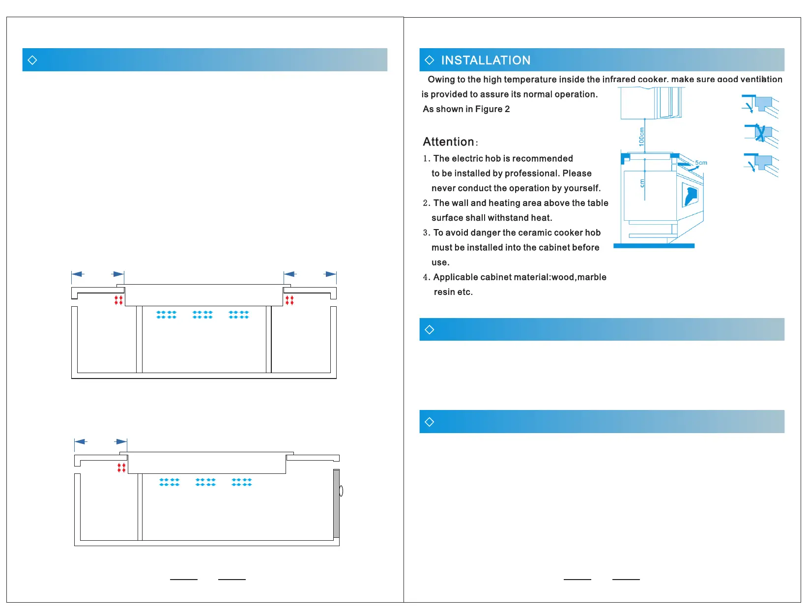
When the machine is embedded, to ensure the normal use of the machine and
better heat dissipation.
Requirements:
1. 30-50mm heat dissipation should be left on the left and right sides and behind.
2. The counter interior should be as large as possible to ensure that enough cold
air is sucked into the machine.
3. Inlet air (cold air) must be separated from outlet air (hot air) space.
4. The air inlet and outlet space of the counter leave air roar.
Positive renderings
30.00 mm
30.00 mm
left
right
Induction cooker
Counter space
Heat flow
The cold air
Exhaust roar
Heat flow
Exhaust roar
30.00 mm
after
Air inlet
Cupboard door
Induction cooker
Heat flow
Exhaust roar
The cold air
Counter space
Side view
HEAT DISSIPATION STRUCTURE INSTALLATION DRAWING
1515
During operation, the surface temperature of the crystal plate is very high.
Please do not touch it to avoid scalding.The appliance shall not be operated
by means of an external timer or independent remote control system.
MATTERS NEEDING ATTENTION
FAULT CODE
E0------- no pot
E1------- The voltage is lower than 90.
E2------- Excessive voltage (voltage higher than 270)
E3------- Furnace surface overtemperature or sensor damage short circuit
E4------- Furnace surface sensor open
E5-------IGBT overtemperature or fan damage does not work
E6------- The IGBT sensor is open
E8------- The control board is connected to the main power supply board
Voltage adaptation range: 90-- 270 VOLTS
 Loading...