10
11
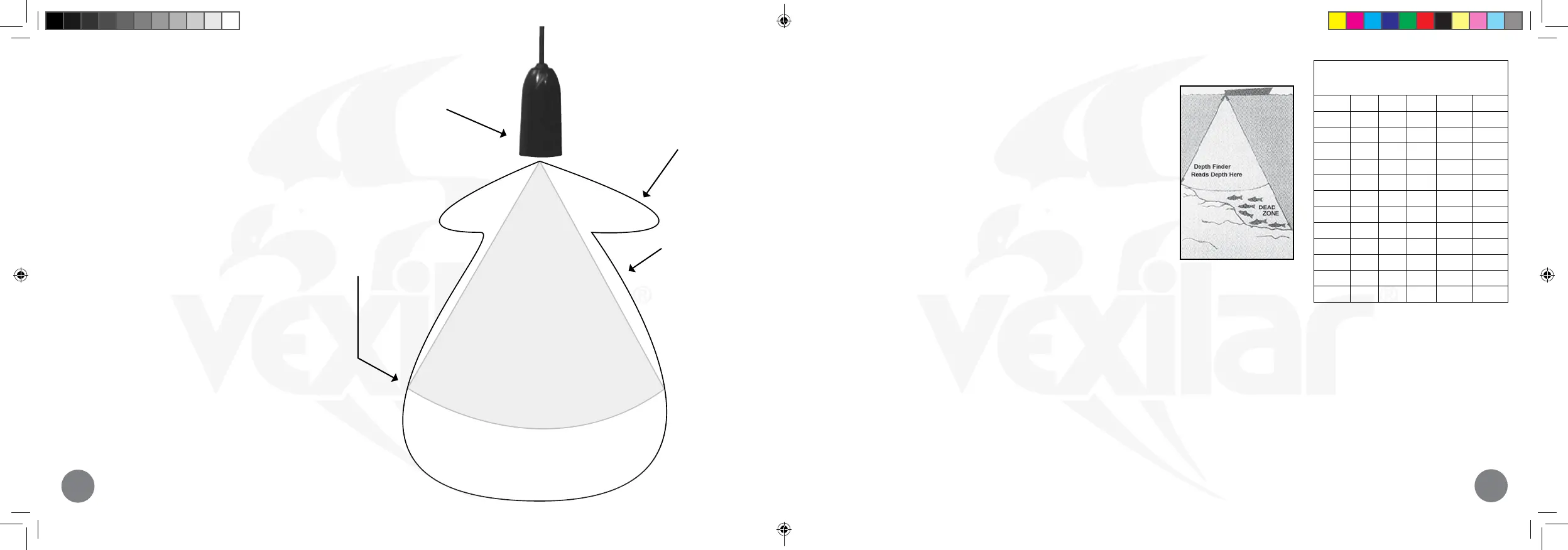
ABOUT TRANSDUCERS
Cone of Sound
The cone of sound is the area the sound waves cover
as they are emitted from the transducer. Generally,
this area is thought of as three-dimensional cone,
such as an upside-down ice cream cone. In actuality,
the cone of sound is not so precisely dened. It is
an irregular shape with edges that taper rather than
end abruptly. Additionally, the cone of sound will
vary slightly from transducer to transducer.
Most objects are visible inside the theoretical cone,
but you can also see objects outside the theoretical
angle yet within the side and main lobes. These
objects must be large enough to suciently reect
the sonar signal. Some of these objects can be
things like the face of a sharp dropping bottom, a
large rock, or even a good size sh or tight group of
smaller sh.
Transducer
Side Lobe
Not all of the sound
waves come out of the
transducer’s bottom.
Some sound comes
out the sides and even
the top.
Main Lobe
The main lobe is
where most of the
sound waves go.
They extend out in
all directions, some
sides more than
others.
Theoretical Cone Angle
The theoretical cone angle
is what the transducer’s
specification defines.
This is the area where the
intensity of the sounds
waves drop to a specific
point (-6dB).
Cone angle vs
Diameter of Coverage
Depth 8° 9° 12° 19° 20°
10’ 1.4’ 1.6’ 2.2’ 3.4’ 3.5
20’ 2.8’ 3.2’ 4.3’ 6.7’ 6.9
30’ 4.2’ 4.7’ 6.3’ 10.0’ 10.6
40’ 5.6’ 6.3’ 8.4’ 13.4’ 14.1
50’ 7’ 7.9’ 10.6’ 16.7’ 17.6
60’ 8.4’ 9.4’ 12.6’ 20.8’ 21.2
70’ 9.4’ 11.0’ 14.7’ 23.4’ 24.7
80’ 11.2’ 12.6’ 16.8’ 26.8’ 28.2
90’ 12.6’ 14.2’ 20.0’ 30.1’ 31.7
100’ 14’ 15.7’ 21.0’ 33.5’ 35.3
120’ 16.8’ 18.9’ 25.2’ 40.2’ 42.3
150’ 21’ 23.6’ 31.5 50.2’ 52.9
DEAD ZONE
Beam angle has a large eect on the performance of your asher. There
is more to it than simply area of coverage. The correct beam angle to use
depends entirely on your application. If you are shing for suspended
sh then you would be pleased with the performance of the 19° cone.
However, if you were going after sh that are holding right on the bottom
along a steep drop-o, you would have better results with the 9°. This is
because of something called dead zone. Dead zone is an area within the
transducer’s cone of sound that is blind to you. The wider the beam angle
the greater the possible dead zone. The sonar will mark bottom as the
nearest distance it sees. If you are shing over a slope, it may see the high
side of the slope, at the edge of the cone, and mark that as bottom. The
sh that are holding on the bottom on the low side of the slope will be
invisible to you because they are actually within the bottom signal on your
depth nder. A narrower beam angle will reduce this eect.
Output Power
Your depth nder puts out a constant amount of power, or sound energy. It does not matter where you have the gain level set. Gain simply controls
how much you amplify the signal that is returned from below. Therefore, a narrow beam transducer will appear to be much more powerful than
a wide beam transducer. This is because you are putting that same amount of power into a smaller area. This can be an advantage if you are
shing in deep water or a detriment if you are shing in shallow water. A narrow beam transducer can be overpowering in shallow water. The
use of the LP (Low Power) Mode on your asher, or the optional S-Cable (page 70), will solve this problem.
Remember to NOT use LP Mode or the S-Cable in depths beyond 20 feet. You will nd that you need to turn your Gain Control up much higher
than normal. This will give a noisy display and make interference from other units much more likely.
The FLX-30 uses a special broad band transducer that oers a wide
spectrum of cone angles that vary with each frequency. The multi-frequency
system has dierent characteristics than the single-frequency transducer
described here. Broad Band transducers do not have side lobes.
Flasher-Family-Manual-2020.indd 10-11Flasher-Family-Manual-2020.indd 10-11 5/20/20 2:16 PM5/20/20 2:16 PM
 Loading...