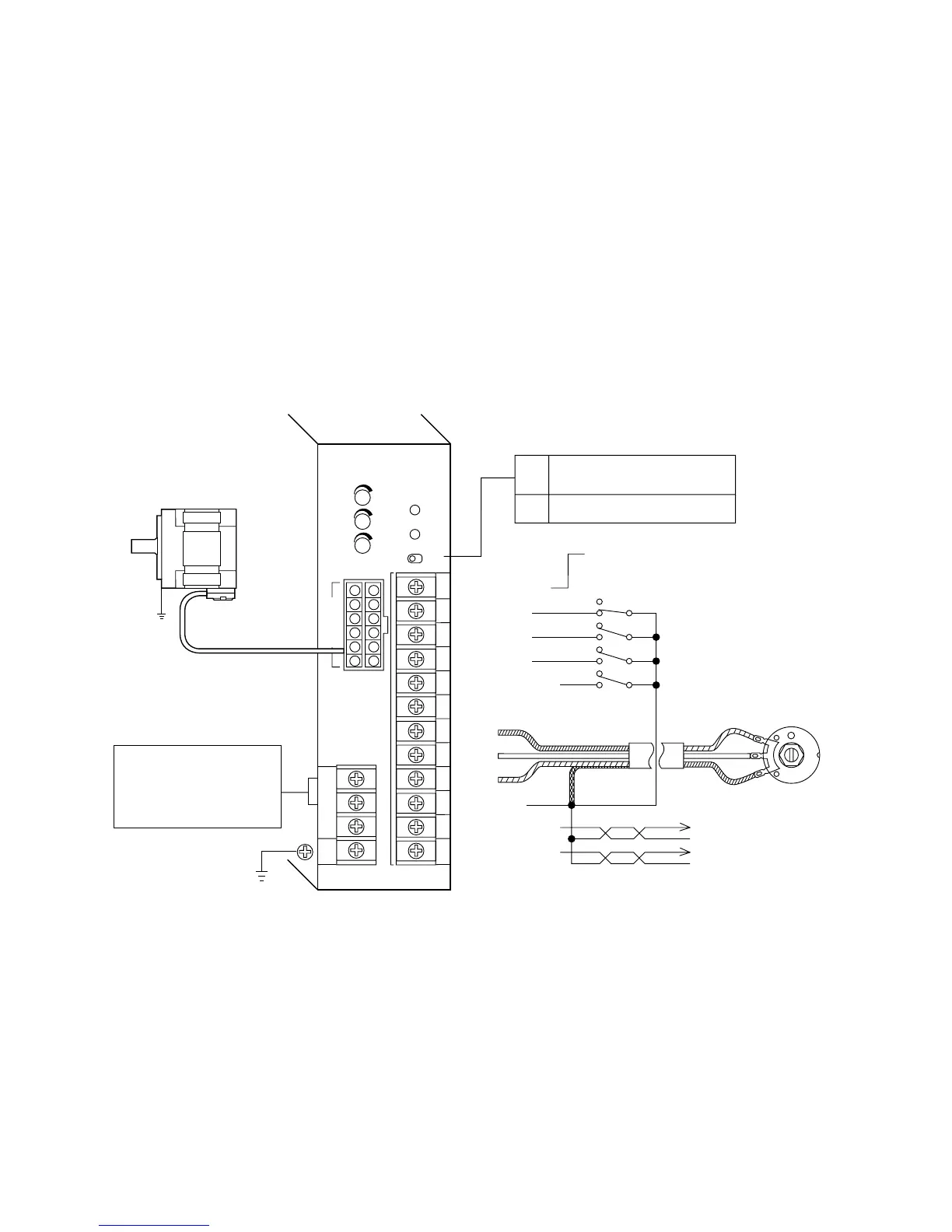
4.2 ExamplesofConnections
・Input/outputsignalinputcanalsobecontrolledbynon-contactmeans(TTL,transistors),aswellasbytheswitches
shownintheabovediagram.Fordetails,seethesection"4. 6 Signal Input Circuits" onpage14.
・Tooperatethemotor,connectthemotoranddriver,andthedriver'ssignalandpowersupplyinput.
Note ・The user must furnish the power supply cable.
・Be sure that the motor connector is fully inserted before turning on power. A loose connection can cause faulty
operation.
・Do not rework or modify the motor cable and extension cable (sold separately). Do not remove the sheath of the cable
and then ground or touch the shielded wire. This may cause electric shock or trigger the ground fault interrupt circuit.
・Be sure to put in the terminal cover after connecting.
■Input power of single phase types
10
1
2
3
3
2
1
4
5
6
7
8
9
10
11
12
INPUT COM
EXT.VR.
CW
CCW
SLOW DOWN
SW1 Speed selection
SW2 Clockwise rotation input
SW3 Counterclockwise rotation input
SW4 Deceleration input
Speed output
GND
Alarm output
GND
N.C.
H
M
L
GND
SPEED OUT
ALARM OUT
EXT.
Set at time of shipment.
When controlling from a programmable
controller or other external power supply.
INT.
When controlling with a relay or switch.
Single-phase100V−115V±10%
(Single-phase200V−230V±10%)
Power capacity varies with output
power of the motor.
Motorcable(0.5m)
Motor
Twisted Pair Line
Shielded wire Speed potentiometer
(accessory)
Protectiveearth
Earth
Driver
External DC power supply+24V
A connection to this terminal is not necessary
when using the driver's built-in power supply.
OFF
ON
OFF
ON
OFF
ON
OFF
ON
1
3
2
S.S.
S.D.
SPEED
FG
N.C.
N
L
BRUSHLESS DC MOTOR
DRIVER FBLD120AW
VEXTA
1
2
3
4
5
6
7
8
9
10
11
12
I/O
POWER
ALARM
EXT.–INT.
MOTOR
 Loading...