2021 RSS Manual all models.doc. Page 5 // 02/12/21
MAINTENANCE
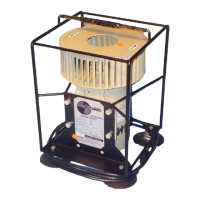
FAN WHEEL SECURITY-After several hours of operation, inspect fan wheel for security of
attachment to the shaft. There are two Allen-head screws, which secure the fan wheel to the 1/2"
shaft. The first indication of looseness of these screws is a slight "rattling" sound emitted from the
wheel during start-up or normal operation. Use the 4mm Allen key (attached to one of the motor
bolts) to tighten these screws per the "FAN WHEEL REPLACEMENT" procedure, below.
FAN WHEEL CONDITION-The fan wheel geometry and RPM precisely determine the sound level
emitted by the RSS. Fan wheel distortions and dust accumulation can alter the sound output. Dust
can be removed with a dry clean brush. Be careful not to dislodge the ½” surge band located around
the top inside of the fan wheel. Substantial fan wheel and surge band repairs may alter the sound
field, and recalibration is advised.
FAN WHEEL REMOVAL-It is strongly advised that the fan wheel not be removed from the motor
shaft. However, if maintenance procedures necessitate this, then proceed carefully as follows. Be
aware that removal may require some effort since a burr may have been formed under an Allen screw
on the motor shaft.
Extreme caution is necessary to avoid damaging the fan wheel, Allen screws and motor
shaft. Loosen the Allen screws two turns counterclockwise. Press the fan wheel upward by hand with
a few pounds (1 kG) force. If it does not come off immediately, then insert a 3/8" (9 - 12 mm)
diameter rod down into the shaft hole and tap it lightly with a hammer while a second person lifts
upward on the Fan wheel with 10 lbs (5 kG) force. When clear of the motor shaft, the wheel can be
slipped upward and to the side to clear the frame. Retain and replace the lock washer spacer on the
shaft. This spacer prevents contact of the Fan wheel to the motor support.
FAN WHEEL REPLACEMENT-
1. With a fine machinist’s file, clear any burrs left by tightened Allen screws from the shaft's
curved (not flat) surface.
2. Verify that the Allen screws are backed out far enough to clear both shaft flats.
3. Align the wheel with an Allen screw facing each flat. Slip the Fan wheel down the 1/2" motor
shaft with less than 2 lbs (1 kG) force. If it binds, do not force it further
4. Remove it, thoroughly file all shaft burrs smooth.
5. Back out the Allen screws to clear the entire wheel bore
6. By hand, pass the back end of a 1/2” (12.7mm) drill bit up through motor end of the wheel
bore.
7. Center the hub on the drill spiral. Rotate the drill to clear hub bore burrs
8. Try installing the Fan wheel on the shaft again. If it still does not go onto the shaft smoothly
try step 4 and 6 again.
Align the fan wheel to face one set screw at the large shaft flat while the other screw falls on
the lesser ground flat. Press the down on the fan wheel with about 2 pounds (1 kg) force and turn in
the Allen screw on the larger flat of the shaft while rapidly rotating the fan wheel fore and aft a few
degrees to assure that this Allen screw is seating on the flat's lowest point.
Torque this Allen screw to at least 30 to 40 inch-pounds (0.35 to 0.45 kg-m). Turn in the
second Allen screw and torque it to 20 to 30 inch-pounds (0.25 to 0.35 kg-m). Caution: Allen key
must be fully inserted into the Allen screw head for this final torque. Improper key seating or torque
applied beyond these values will damage the Allen screw**
 Loading...