16
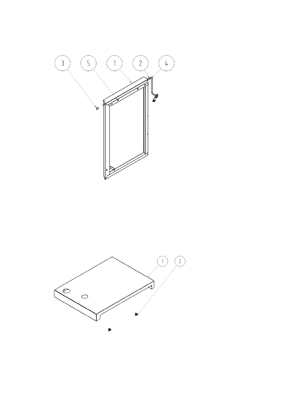
5. Mount two connecting plugs (5), into the left side part of the jacket (1), insert the bushings (2, 3), then
insert the draw bar of the smoke flap control (4) and the insulation. Put the jacket on the lower anchor
bolts and connect the upper part with consoles 1 and 2 by means of two screws M5 x12 and two
washers 5,3 – see Fig. no. 13.
Fig. No. 13 Left side part of the jacket
6. Mount the insulation of the rear part of the jacket (9 – Fig.no.15; 14 – Fig.no.18) and screw to the side
parts of the jacket by means of screws ST 4,2 x 9,5 (10 – Fig.no.15; 15 – Fig.no.18).
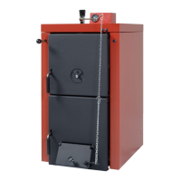
Mounting of the upper part of the jacket in case of boiler without the control box (see Fig.no.14):
1. Mount four spring clips (2) on the upper part of the jacket (1) and insert the thermomanometer (8 –
Fig.no.15).
Fig.no.14 Upper part of the jacket in case of boiler without the control box
2. Insert the thermometer sensors into thermometer well and screw the manometer sensor into the
manometr well. .
3. Insert the insulation into the upper part of the jacket and put the whole assembly on the boiler. .
1. Upper part of the jacket
2. Spring clip
1. Side part of the jacket
2. Bushing HEYCO
3. Slant bushing
4. Draw bar of the smoke flap
control
5. Connecting plug


 To Next Page