EasyManua.ls Logo

Viavi T-BERD MTS 5800-100G User Manual

Viavi T-BERD MTS 5800-100G
296 pages
To Next Page IconTo Next Page
Page #1 background imageLoading...
Page #1 background image
T-BERD/MTS/SC Getting
Started Guide
T-BERD/MTS 5800, 5800-100G,
MSAM, CSAM, DMC, and SC 4800/
4800P

Table of Contents

Question and Answer IconNeed help?

Do you have a question about the Viavi T-BERD MTS 5800-100G and is the answer not in the manual?

Viavi T-BERD MTS 5800-100G Specifications

General IconGeneral
BrandViavi
ModelT-BERD MTS 5800-100G
CategoryTest Equipment
LanguageEnglish

Summary

T-BERD/MTS/SC Getting Started Guide

Product Regulatory Compliance

Federal Communications Commission (FCC) Notice

FCC compliance statement for Class A digital devices, including operational conditions and interference mitigation.

Industry Canada Requirements

Industry Canada compliance statement for license-exempt RSS standards, including operational conditions and interference mitigation.

Safety and compliance information

Chapter 1 Overview

About the instruments

Describes the T-BERD/MTS MSAM, CSAM, 5800, 5800-100G, and Smart Class 4800/4800P as all-in-one test solutions.

Features and capabilities

Lists instrument features like electrical/SONET/SDH/Ethernet/FC/OTN interface support and optical power measurement.

Configuring your instrument

Explains that instruments are factory-configured and how to discuss specific configurations.

About the T-BERD / MTS 5800 and SC 4800

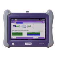
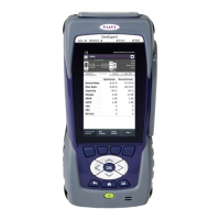
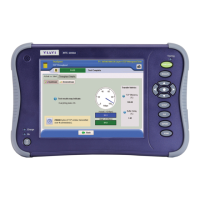
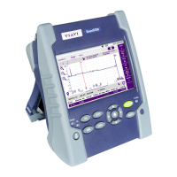
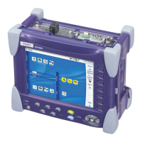
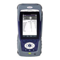
Describes the T-BERD/MTS 5800 and SC 4800/4800P as rugged, portable test solutions.

About the CSAM Assembly

Describes CSAM usage with 6000A or 8000 base units and DMC chassis.

About the MSAM Assembly

Describes MSAM usage with 6000A or 8000 base units and DMC chassis.

About the DMC Assembly

Describes DMC chassis usage with T-BERD/MTS 8000 base unit for testing multiple circuits.

Features and capabilities

Configuring your instrument

Optional Expansion Modules

About the T-BERD / MTS 5800 and SC 4800

Configuring the T-BERD / MTS 5800 and SC 4800

About the CSAM Assembly

About the MSAM Assembly

Handling SFP/SFP+, XFP, and QSFP+ transceivers

Chapter 2 Assembling Your Instrument

Preparing for assembly

Instructions to review before unpacking and assembling instrument components.

Connecting a DMC to a base unit

Details key principles and base unit requirements for connecting a DMC to a base unit.

Inserting MSAMs or CSAMs into the 6000A base unit or DMC

Steps for inserting MSAM or CSAM modules into the 6000A base unit or DMC chassis.

Inserting, removing, and swapping PIMs in the MSAM

Instructions for inserting, removing, and swapping Physical Interface Modules (PIMs) in the MSAM.

Attaching an expansion module to the 5800v2/100G and 5882

Procedure for attaching optional expansion modules to specific instrument models.

Handling CFP adapters and transceivers

Guidance on inserting and removing CFP adapters and transceivers.

Handling SFP/SFP+, XFP, and QSFP+ transceivers

Provides guidance on inserting and removing SFP, SFP+, XFP, and QSFP+ transceivers.

Preparing for assembly

Key principles

Principles for secure connection and avoiding damage when connecting/disconnecting components.

Verifying the base unit requirements

Checks base unit requirements before connecting a DMC to ensure compatibility.

Connecting a DMC to a base unit

Verifying the requirements on a base unit

Connecting the DMC to a base unit

Inserting MSAMs or CSAMs into the 6000A base unit or DMC

MSAM requirements

Checks MSAM compatibility with DMC and power supply requirements.

CSAM requirements

Checks CSAM compatibility with 6000Av2 base unit and power supply requirements.

Inserting the MSAM or CSAM

Step-by-step guide for inserting MSAM or CSAM modules into the instrument.

Inserting, removing, and swapping PIMs in the MSAM

Inserting a PIM

Steps for inserting PIMs into the MSAM ports, ensuring correct compatibility and orientation.

Swapping PIMs

Attaching an expansion module to the 5800v2/100G and 5882

Handling CFP adapters and transceivers

Inserting a CFP adapter

Steps for inserting CFP adapters into CSAM ports to provide physical interfaces.

Inserting a CFP, CFP2, or CFP4 transceiver

Chapter 3 Getting Started

Powering the instrument

Details how to power the instrument using battery or AC adapter, and verifying correct adapter.

Launching the MSAM or CSAM

Instructions on launching MSAM or CSAM modules, including BERT icons and system screen navigation.

Navigating the user interface

Describes the instrument's user interface elements like Menu Bar, Soft keys, and Result Windows.

Setting up the instrument

Covers tasks like loading software, setting screen saver, specifying printer, and VNC password.

Connecting your instrument to the circuit

Guidance on connecting the instrument to the circuit, considering older/newer chassis and PIM requirements.

Connecting your instrument to the circuit

Configuring Expert Optical settings

Setting up the Job Manager

Chapter 4 Basic Testing

Preparing to test

Recommendations before testing, including verifying cables and determining synchronization needs.

Step 1: Selecting a test application

Methods for selecting a test application using Quick Launch or Test Menu.

Step 2: Configuring a test

Process of displaying setup screens, specifying test settings, and saving configurations.

Step 3: Connecting the instrument to the circuit

Basic instructions for connecting the instrument to the circuit for testing.

Step 4: Starting the test

Steps to start a test after configuration and connection, including laser control.

Step 5: Viewing test results

How to view test results in Results Windows, including grouping and layout options.

Running multiple tests

Guidance on running multiple tests simultaneously to reduce testing time.

Creating and printing reports

Process for formatting, creating, storing, and printing reports with optional screen shots.

Preparing to test

Understanding synchronization requirements

Explains how synchronization with external timing references improves measurement accuracy.

Connecting the GPS receiver to your instrument

To connect the TM4-M GPS receiver to your instrument

Detailed steps for connecting the TM4-M GPS receiver to various instrument models.

Configuring GPS as the time source

Understanding external high accuracy timing references

Using the 5800v2 and 5800-100G to provide high accuracy external timing

Preparing for optical testing

Considerations

Factors to consider before optical circuit testing, including optics and transceiver details.

Verifying supported line rates

Tuning SFP+ and XFP transceivers

Testing Optics and Cables

Running the Optics Self-Test and Cable Test

Steps to run the Optics Self-Test and Cable Test applications.

Testing Active Optical Cables and Direct Attach Copper cables using T-BERD/MTS 5800-100G and 5800v2

Step 1: Selecting a test application

About the Quick Launch screen

Allows selecting and running pinned and recently used tests quickly.

Launching a test from the Quick Launch screen

Launching a test using the Test Menu

Step 2: Configuring a test

Displaying the setup screens

Steps to display setup screens by selecting a test application and then the Setup soft key.

Entering data in the setup fields

Saving setups

Step 3: Connecting the instrument to the circuit

Step 4: Starting the test

Controlling laser transmission

Step 5: Viewing test results

Setting the result group and category

Steps to set result group and category using Group and Category buttons.

Creating and maintaining Custom result groups

Running multiple tests

Viewing both tests

Scheduling timed tests

To schedule a timed test

Steps to schedule a timed or delayed-start timed test, specifying duration and time.

Creating and printing reports

Specifying report details

How to specify details like owner, serial number, technician name for the report header.

Creating a report

Generating reports automatically

Viewing a report

Exporting reports

Running a VT-100 session

Chapter 5 Smart Access Anywhere

Launching the utility

Steps to launch the utility on the instrument and workstation for remote access.

Establishing a connection

Launching the utility

To launch the utility on your instrument

Procedure to launch the utility on the instrument to obtain the remote access code.

Testing your connection

Displaying the instrument’s user interface

Transferring files

Displaying and modifying connection settings

Chapter 6 Using Bluetooth Connections

Setting up a Bluetooth connection

Steps to enable Bluetooth, allow pairing, and find devices for connection.

Setting up a Bluetooth connection

Transferring files via Bluetooth

Using a Bluetooth audio device

Disconnecting and unpairing Bluetooth devices

Deactivating Bluetooth

Chapter 7 Optical Tools

Inspecting fiber

Details the use of the Viavi fiber microscope accessory for fiber inspection.

Measuring optical power

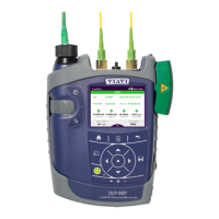
Explains how to use the Optical Power Meter accessory for power measurements.

About the optical tools

Inspecting fiber

To inspect fiber

Steps to connect and use the fiber microscope for inspection.

Measuring optical power

Appendix A Specifications

T-BERD / MTS 5800 and Smart Class 4800 specifications

Provides detailed specifications for T-BERD/MTS 5800 and SC 4800 instruments.

MSAM specifications

Lists specifications for the MSAM and its available PIMs.

Jitter and Wander specifications

Details specifications for jitter and wander measurements for MSAM and T-BERD/MTS 5800.

CSAM specifications

Provides specifications for the CSAM module.

T-BERD / MTS 5800 and Smart Class 4800 specifications

MSAM specifications

X.21 interface specifications

RS-232/V.24 interface specifications

EIA-530/EIA-530A balanced interface specifications

E3/DS3/STS-1 PIM specifications

Receiver (DS3 circuits)

Transmitter (DS3 circuits)

Receiver (STS-1 circuits)

Transmitter (STS-1 circuits)

E4/STM-1e PIM specifications

SFP/SFP+/SFP28 specifications

XFP PIM specifications

Optical specifications

CSAM specifications

DMC specifications

Appendix B Maintenance and Troubleshooting

Maintaining the T-BERD/MTS 5800 and SC 4800 batteries

Provides guidelines for maintaining the rechargeable lithium-ion battery for T-BERD/MTS 5800 and SC 4800.

Enabling the software option

Updating the software

Installing the software using a USB stick

Updating over a network connection

About troubleshooting

Assembly and setup

Operating the instrument

Instrument will not power up

Performing tests

Test results are inconsistent

Maintaining your instrument

Battery communication

Appendix C Storage and Shipment

Storing the instrument

Shipping the your instrument

Returning equipment to Viavi

Related product manuals