2.5 Grounding Connection
A ground lug and mounting screw are included in the
Legend 9). Connect a No. 18 AWG ground wire to the
accessory kit. Use the mounting hole located above the
nearest earth ground.
control cable connector to attach the lug. (Figure 5,
2.6 Adjusting the
After the cable is assembled and the unit connected, plug
the control unit into a 120 VAC source and proceed as
follows:
1. Loosen the two (2) pan limit stops (Figure 5,
Legend 1 and 2).
2.
Move the joystick to the RIGHT, rotating the pan
head clockwise until the desired right pan limit is
reached.
3.
Locate the right pan limit stop (Legend 2) and move
it until it contacts the limit-switch actuator (Legend
8). Move the stop a slight distance further to the
deflect actuator until a “click” is heard, indicating
deflection of the actuator and opening of the limit
switch. Lock the stop in place.
4.
Move the joystick to the LEFT to rotate the pan head
to the desired left limit position.
Adjust the left pan
limit stop (Legend 1) in the same manner as the right
pan limit stop.
5. Wth both limit stops in place, pan to both stop
positions and recheck for exact trim of limit stops.
Tighten both stops securely.
6.
7.
8.
9.
Limit Stops
Looking at the front of the unit, remove the two (2)
screws (Legend 7) from the left end plate. Remove
the plate.
Loosen screws (Legend 3 and 4) and move the
joystick UP to rotate the tilt drive to the desired up
limit.
Move the
uplimit
stop (Legend 3) toward the bot-
tom end of the slot until a “click’ can be heard.
Tighten screw.
Move the joystick DOWN to rotate the tilt drive to
the desired down position,
10. Adjust the down-limit stop (Legend 4)
in
the same
manner as the up-limit stop.
11.
Lock the limit stops securely in place and check for
exact trim of limit stops.
12. Replace the left end plate and screws.
2.7 Preset Adjustments
CAUTION:
Vicon does not recommend use of the
A
preset position option in units intended for
autopan use. Such use will cause excesive wear
to internal preset components and voids product
warranty.
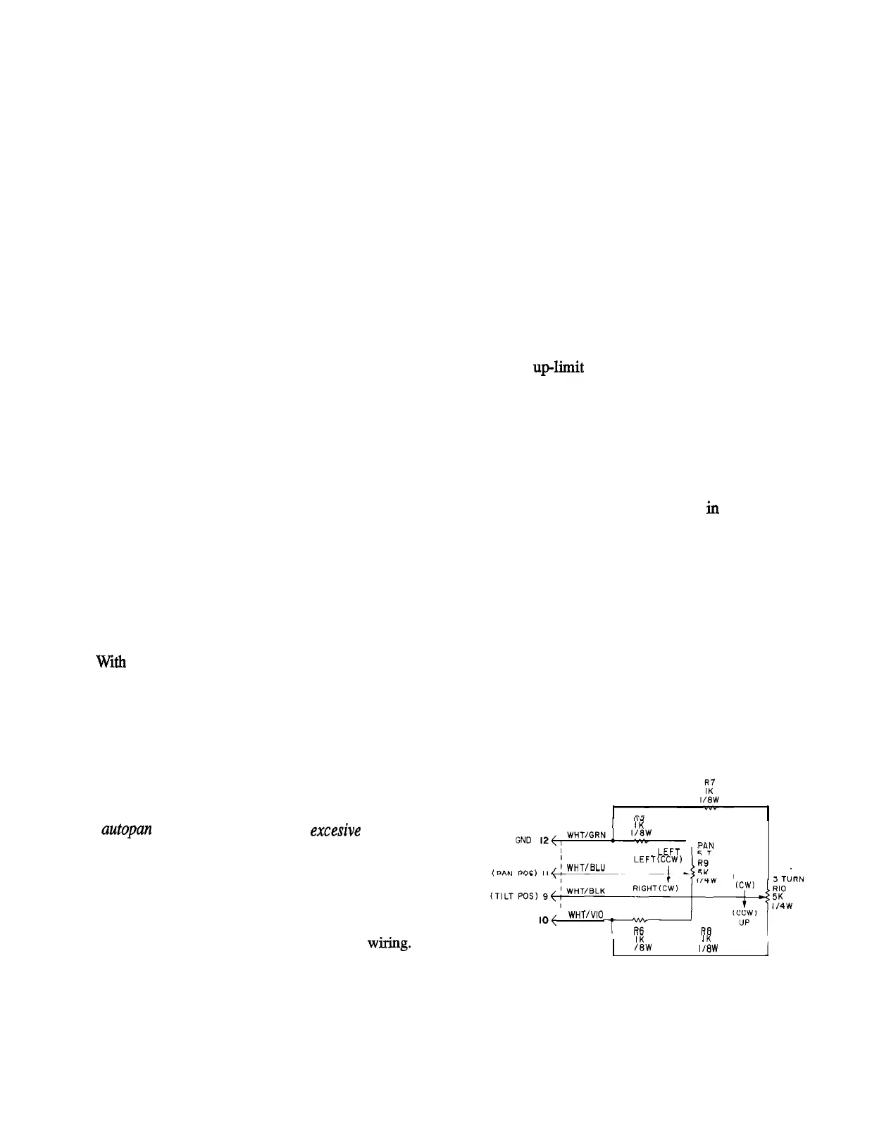
If a unit equipped with a preset position option is
disassembled, contact Vicon for reassembly and align-
ment instructions. Also see Figure 6 for preset
wiring.
1 IK
1 PBN
URN
SUPPLY
IO{
I WHT/VIO
DOWN
TILT
I IK
IK
I
I /8W 1/8W
1
6
Figure 6
Preset Wiring Diagram
X433-893