6
1A) Initial Design Considerations
The scope of this document is not intended to be a resource or white paper on VAV zoning system design.
There are many good resources available on the subject of VAV zoning systems and their associated
advantages and disadvantages. Please consult these resources for further information on this subject.
It is the responsibility of the designer and installer to ensure the following considerations are met:
• Size the installed equipment for properly calculated heating and or cooling peak loads. There are no
advantages to over sizing the system’s capacity to more than what is required as this simply leads to
short cycling of the equipment during small load periods.
• Properly size and layout all ductworks including the by-pass damper according to local codes and
standards in effect.
• Properly size the capacity of the zones according to the actual requirements of the room. Using
square footage calculations only can create situations where the installed total deliverable load may
be insufficient for the actual intended use of an area. Conference rooms, computer rooms, cafeterias
or other rooms where large gatherings occur would be a prime example of this scenario.
It is not the mandate of the zoning control system to correct for wrong initial mechanical layout and or load calculations
of the mechanical equipment. The control system will attempt to deliver the loads required by master demanding zones
by distributing the total available capacity of the installed equipment to the required demanding areas. If the equipment
is undersized for the required peak loads, the control system will distribute the available capacity according to the
priorities requested hence making most of the areas comfortable.
Proper planning and design will ensure that a job site will be up and running faster with less service calls
during the initial occupancy period.
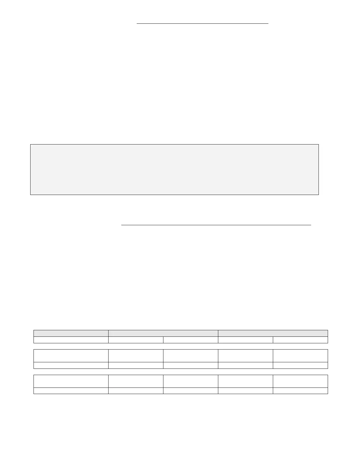
1B) Scalability and Limitations
The system is fully scalable in terms of number of zone controllers and RTU controllers used on the same
network layer (BACnet MS-TP or Wireless models).
BACnet controller system overview:
A BACnet MS-TP network segment is a single 22 gauge shielded network wire loop run between all
devices communication connections that is no longer than 1200 meters (4000 feet). It is possible to install
up a maximum of 64 nodes on a single network segment.
To install more than 64 nodes or if the network wire loop is longer than 1200 meters (4000 feet), repeaters
will be needed for proper communication. Please refer to the BACnet integration guide if repeaters are
required. With the proper use of repeaters, the maximum number of nodes on a single BACnet MS-TP
trunk can be extended to 128 nodes.
Smallest System Supported Largest System Supported
Number of Zones Number of RTUs Number of Zones Number of RTUs
Single Segment of 64
nodes maximum
1 zone reporting to 1 RTU Minimum 63 zone reporting to 1 RTU Minimum
32 zone reporting to 32 RTU Maximum
Single Network trunk of
128 nodes maximum
1 zone reporting to 1 RTU Minimum 126 zone reporting
to
1 RTU Minimum
63 zone reporting to 63 RTU Maximum
With BACnet supervision devices and multiple systems installed on a job site, there is no practical limit to
the number of zone and RTU controllers which can be installed on a single job site.
 Loading...