Do you have a question about the Viconics VT7600 Series and is the answer not in the manual?
Proper placement for optimal performance and airflow, avoiding heat sources and direct sun.
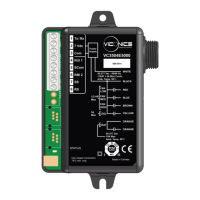
Step-by-step instructions for securely mounting the controller and connecting wires.
Details wiring for various system types, including multistage and heat pump configurations.
Illustrates specific terminal layouts for top and bottom connectors on the controller.
Important notes on wiring main outputs, jumpers, and digital inputs for system operation.
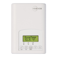
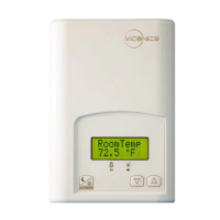
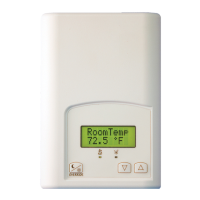
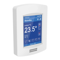
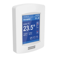
Describes the controller's two-line display, auto-scrolling status, and manual scrolling.
Explains the menu-driven interface for setting parameters like temperature, time, and system mode.
Details the function of each key for navigation, confirmation, and parameter adjustments.
| Display | LCD |
|---|---|
| Mounting | Wall Mount |
| Enclosure Rating | IP20 |
| Operating Temperature | 32°F to 122°F (0°C to 50°C) |
| Power Supply | 24VAC, 50/60Hz |
| Communication Protocol | BACnet MS/TP |
| Dimensions | 120 mm H x 84 mm W x 28 mm D |