Do you have a question about the Victron energy ET112 and is the answer not in the manual?
Details the items included with the Wireless Sensor gateway, such as RJ45 cable and AC adapter.
Steps to connect the Wireless Sensor gateway to the network and power source.
Instructions for physically connecting the AC sensor to each phase of the system.
Procedure for pairing sensors with the gateway using LED indicators and button presses.
Explanation of the LED status codes on the AC sensor and their meanings.
Steps to navigate the Color Control menu to configure the gateway and assign sensor locations.
How to access and view the measured voltage, current, power, and energy values.
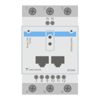
Details electrical ratings, measurement precision, and environmental operating limits.
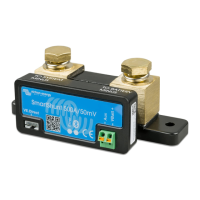
The Victron Energy Wireless AC Sensor is a device designed to measure and calculate various electrical parameters in a PV (Photovoltaic) Inverter system, including current (A), voltage (V), power (W), and energy (kWh). This data is then displayed on a Color Control GX and the Victron Remote Management (VRM) Portal, providing users with comprehensive monitoring capabilities for their solar energy systems.
The core function of the Wireless AC Sensor is to provide accurate electrical measurements for PV Inverter systems. It operates as part of a larger system that includes a gateway, which acts as the DECT (Digital Enhanced Cordless Telecommunications) hub for the sensors. Each system requires one gateway, and one sensor is used per phase of the AC power system. The gateway connects to the Color Control GX via Ethernet, facilitating data transfer and system integration. Multiple sensors can connect to a single gateway, allowing for scalable monitoring solutions.
A key feature is its ability to handle both single-phase and three-phase systems. For three-phase systems, the manual recommends using a dedicated three-phase meter rather than three single-phase meters, as this provides more accurate and true three-phase measurements. The system is designed to prevent the use of multiple sensors on the same position (e.g., AC-Out, AC-In 1), ensuring data integrity; in such cases, the Color Control GX will only display the value from the last-read sensor.
The system comprises two main hardware components: the Wireless AC sensor itself (TIM000100100, available in a 25A rating) and the Wireless Sensor gateway (TIM000100000). The gateway package includes a 30cm RJ45 cable for Ethernet connection and an AC adapter for power. Notably, the gateway can also be powered directly from one of the USB ports on the Color Control GX, offering flexibility in installation. However, due to power limitations of the CCGX-USB port, this alternative power method cannot be combined with other USB accessories like a USB-GPS or USB-WiFi if a non-powered USB hub is used.
Installation of the gateway is straightforward, involving three steps:
For the sensors, installation involves connecting each AC sensor according to a schematic, ensuring the neutral is on the top side and the line on the bottom side, with correct current direction.
A crucial aspect of usage is the pairing process between the gateway and sensors. Upon initial power-up, a sensor will blink red, indicating it's not yet paired. If both green and red LEDs are on, it signifies that the sensor needs to be unpaired first by pressing and holding the reset button until the LED blinks red. To initiate pairing, the button on the gateway is pressed for 5 seconds, causing its LED to blink red (slowly at first, then fast along with the sensor's LED). Once a sensor is found, its LED will briefly blink orange. The discovery process can take between 30 seconds and 12 minutes, with longer times potentially indicating a software update. After successful pairing and any updates, the sensor LED will turn off, and the gateway LED will show green with short intermittent red blips, indicating normal operation.
Configuration is done via the Color Control GX. Users navigate to "Settings → Wireless AC Sensors" to access the menu. The gateway, once connected to the network, will appear in a list. Connected AC sensors will also be listed, initially by their ID number. Users must then select each sensor and assign a specific location (e.g., AC-In1_L3) for proper functionality.
Once configured, the measured values can be viewed in the Device List on the Color Control GX. For example, selecting "PV Inverter on AC In1" will display detailed readings for each phase (L1, L2, L3), including voltage, current, and power, as well as total current, total power, and accumulated energy (kWh).
The Wireless AC Sensor system is designed for specific electrical environments:
The manual does not explicitly detail maintenance features in a dedicated section. However, the LED indicators on both the gateway and sensors serve as important diagnostic tools, aiding in troubleshooting and confirming operational status.
These LED states allow users to quickly assess the status of their sensors and gateway, facilitating prompt identification of pairing issues, connectivity problems, or normal operation. The reset button on the sensor is also a key maintenance feature, allowing users to unpair a sensor if needed, which is essential for re-pairing or reconfiguring the system. The software update process, which can occur during the initial discovery phase, ensures the devices run on the latest firmware, contributing to system stability and performance.
| Brand | Victron energy |
|---|---|
| Model | ET112 |
| Category | Measuring Instruments |
| Language | English |