5
INSTALL SHEET
OMV OUTDOOR MOTION VIEWER
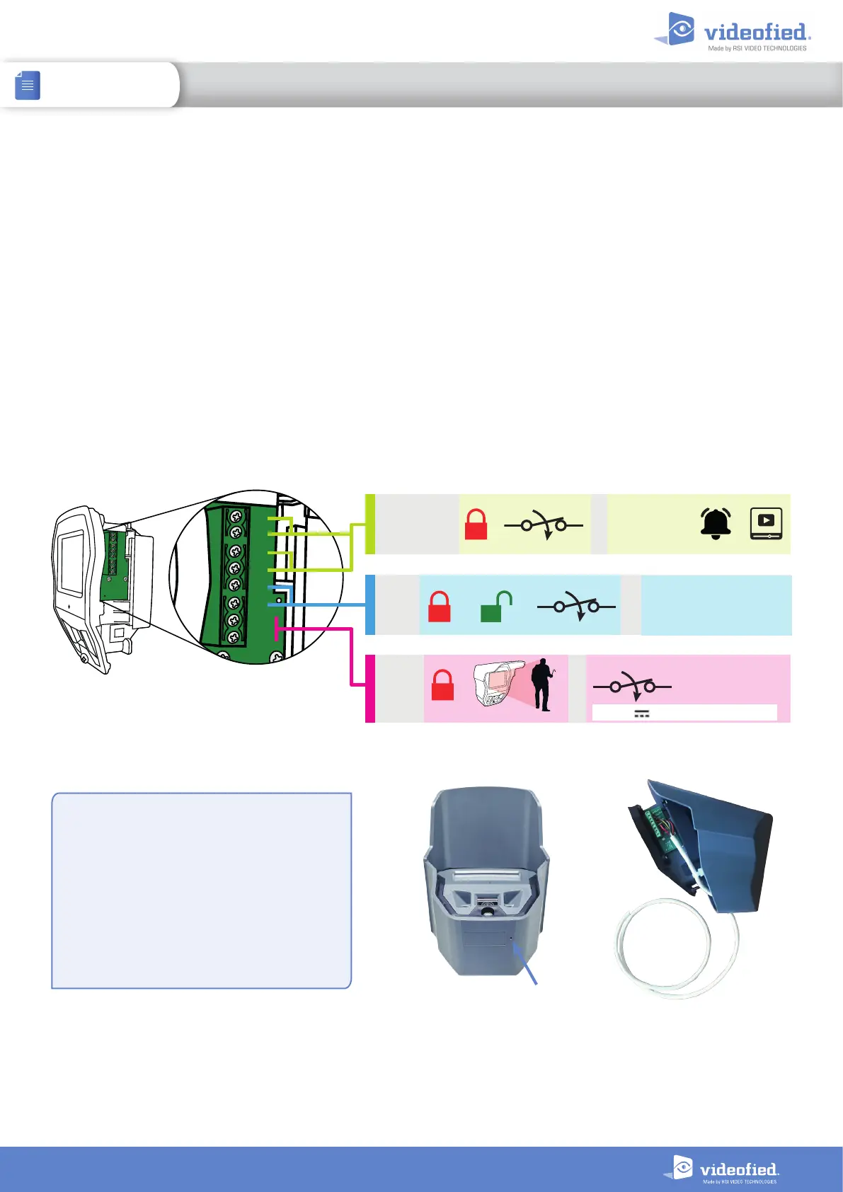
Wired inputs/output
The OMV MotionViewer has 3 built-in wired inputs. With these inputs, other detection systems can be associated
with the OMV.
IN1 and IN2 inputs : Normally open wired inputs. These inputs are enabled when the OMV is armed. When
triggered, an INTRUSION event is sent to the panel and the OMV captures a video.
IN3 input : Normally open wired input. This input is enabled 24/7. When triggered, a TAMPER event is sent to the
panel.
The OMV also has one built-in wired output. This output can activate a wired system when the OMV infrared
detection is triggered.
OUT output : 24 V/10 0mA open drain contact. When the OMV is triggered, the output contact closes for 3
seconds and opens.
Inputs/outputs wiring
Two drilling punch marks are visible on the OMV
case. One under the case and one inside the box on
the bottom right.
Drill a hole in one of these punch marks to pass
the wire through and connect the inputs/outputs
terminal.
IMPORTANT :
Once the wire is connected, protect the inside of
the case with a silicone watertight seal.
Punch mark
OUT+
OUT–
IN3
IN2
IN1
GND
GND
GND
OUT+
OUT–
IN3
IN2
IN1
GND
GND
GND
IN3 : or + = TAMPER
IN1 or IN2 : + = INTRUSION + +
OUT : + = (3 seconds)
Max 24VDC / 100 mA
 Loading...