3-14 Connector Panel Rev AA
Videojet 1710 Operator Manual
Note: All the connectors are sealed to provide the required protection from water
and dust according to the IP65 standard.
Pinout Information
Connector Pinout
Print Trigger 2 (Reverse Print) DIN 3 Pin
Status Output (Lampstack) DIN 6 Pin
Shaft Encoder DIN 4 Pin
Relay Switches DIN 7 Pin
Table 3-1: Connector Pinout Information
Cat 5e
1
2
3
4
5
6
7
8
9
10
11
12
PCB 1
PCB 2
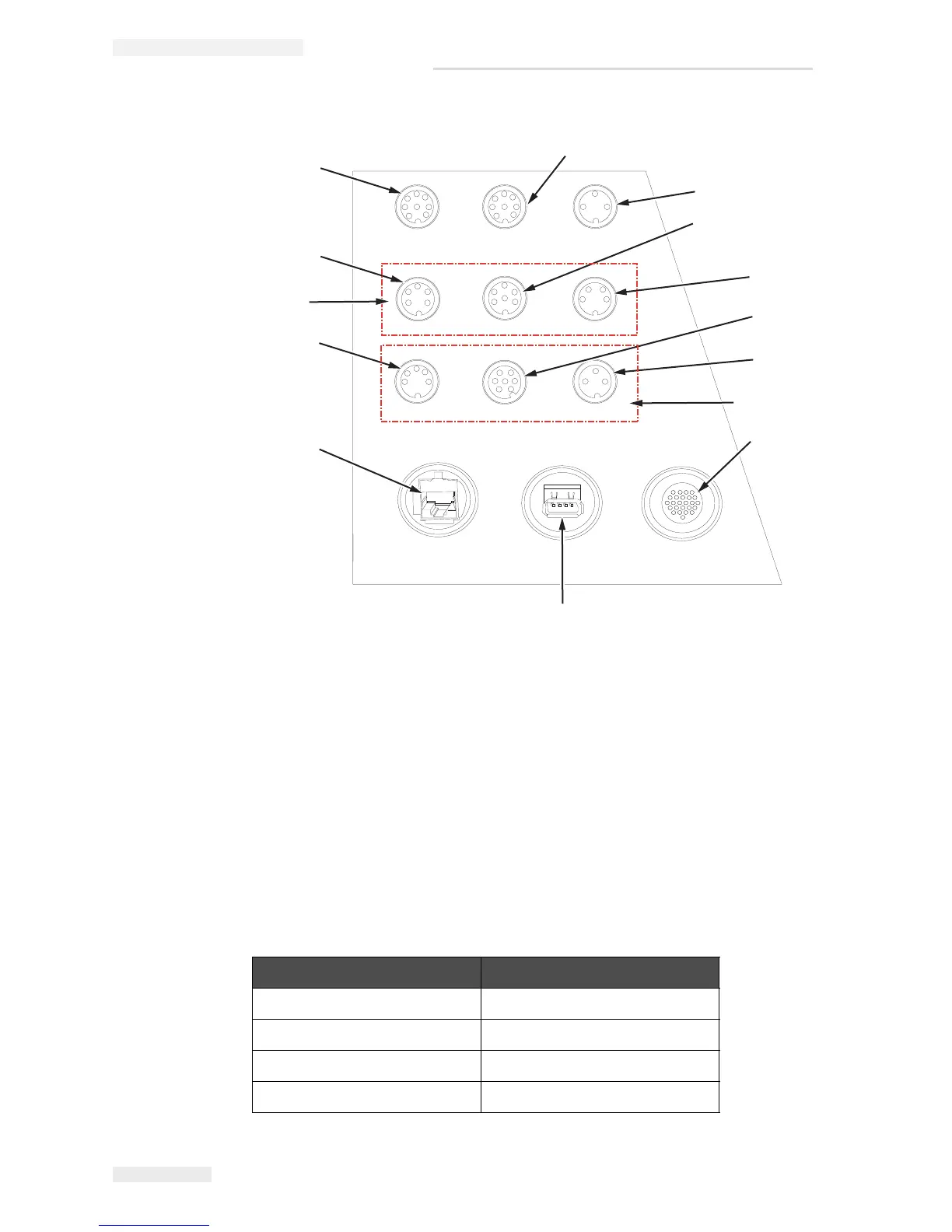
1. Message A Input*
2. Print Trigger 2 (Reverse Print)*
3. Status Output (Lampstack)
4. Shaft Encoder
5. Relay Switches
6. Print Trigger 1
7. I/O 25 Way*
8. USB
9. Ethernet*
10. COMMS RS485
11. COMMS RS232
12. Message B Input*
Figure 3-13: IP 65 (Optional) Printer Connector Panel
* - Optional Connectors