VP220D & VP220-3 Installation Guide | 6
430880-101
(Rev. 10/21) Copyright 2021 VideoProtects Incorporated. All rights reserved.
Step 4 – Connect power supply
There are three ways to provide power to the camera:
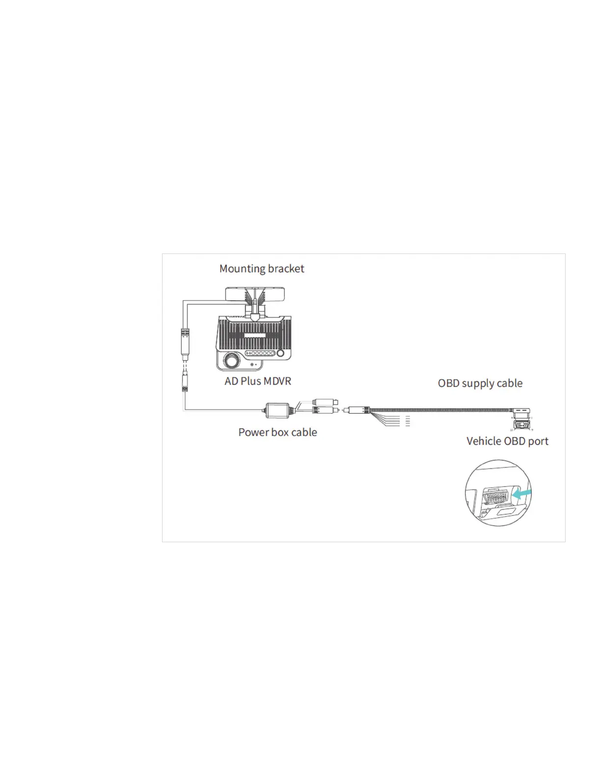
1) Quick plug-in OBD-II power cable adapter (ordered separately)
If using the OBD-II power supply connection, plug the power box cable into the camera.
Then, connect the OBD-II quick plug to the power box cable. Route the assembled cable
up under the headliner, and down the A pillar into the dashboard area near the OBD-II port
on the vehicle. Plug the OBD-II quick connector into an available OBD-II port. Secure the
cables under the dashboard with zip ties.
NOTE: An OBD-II T harness (ordered separately) will be required to provide multiple
OBD-II ports for connecting the camera and a GO device.
2) Quick plug-in 9 pin power cable adapter (ordered separately)
If using the 9-pin power supply connection, plug the power box cable into the camera.
Then, connect the 9-pin quick plug to the power box cable. Route the assembled cable
up under the headliner, and down the A pillar into the dashboard area near the 9-pin port
on the vehicle. Plug the 9-pin quick connector into an available 9-pin port.
NOTE: A 9-pin T harness (ordered separately) might be required to provide the appropriate
ports for connecting the camera and a GO device.