66251090-EN - V2.1 - 15/05/16
4000 Series
Art.4833 - Installation instructions
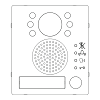
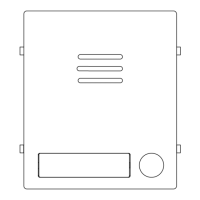
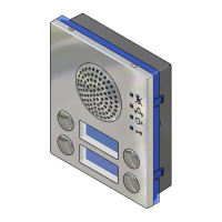
Art.4833 Speaker unit
SETTINGS DIPSWITCH & JUMPERS
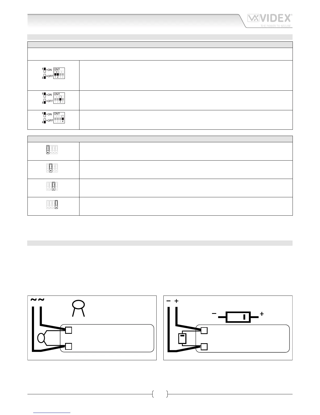
4 WAY DIPSWITCH
First two switches are used to set the speaker unit address: the speaker unit address is required for camera recall operation on 2
or more entrance systems.
Switches 1,2 Unit Address
OFF OFF 1
ON OFF 2
OFF ON 3
ON ON 4
Switches 3 Conversation Time
OFF 60 seconds
ON 120 seconds
Switch 4 Door opening time (J2 = “L” position)
OFF 2 seconds
ON 6 seconds
JUMPERS J1, J2, J3, J4
J1 Position Call reassurance tone volume
H High
L Low
J2 Position Door open relay operating mode
H Capacitor discharge
L Dry contacts
J3 Position Call buttons operating mode (only for Art.4833)
H Each button calls a dierent videophone
L Both buttons call the same videophone (Address 1)
J4 Position Built-in relays – back EMF protection (MOV)
H NC contact
L NO contact
When the door open relay operating mode is set to “capacitor discharge”, one terminal of the electric lock must be connected to
ground while the second must be connected to “NO” terminal. The “NO” terminal will supply a temporary voltage when the speaker
unit receives the door open command.
BUILTIN RELAYS BACK EMF PROTECTION
The Art.4833 includes selectable back EMF protection on the relays. The jumpers marked J4 (One jumper for each relay) are used to
select the protection type. When using a fail secure lock with connections C & NO the jumper should be in the NO position. When using
a fail open lock with connections C & NC the jumper should be in the NC position and when using the codelock to trigger a gate con-
troller or another third party controller the jumper should be removed completely (This disables the protection on the relay).
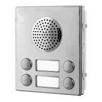
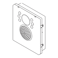
LOCK RELEASE BACK EMF PROTECTION
A varistor must be tted across the terminals on AC lock release
and a diode must be tted across the terminals on a DC
lock release
(Fig.1B) to suppress back EMF voltages. Connect the components to the lock releases as shown in gures.
VARISTOR (MOV)
12V AC
LOCK RELEASE
Fig.1A
1N4002
12V DC
LOCK RELEASE
Fig.1B