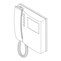
Two Wire Videokit ESVK Series
PrtCode:ESVK_ENG_1.3 – Pag.9/24
23/10/2008 Rev.1.3
PROGRAMMING
After each programming operation carried out through dip-switches or jumpers it is necessary to temporary disconnect the videophone from the BUS or
from the power supply if locally powered.
NUMBER OF RINGS
The number of rings can be set to 3 (factory preset) or 6.
To change the number of rings proceed as follow:
- Unplug the flat cable from the pcb connection board;
- Put in short the terminals 13 and 14;
- Plug-in the flat cable checking the privacy on LED and remove the short between terminals 13 and 14;
- The number of LED flashes will be 1 for 3 rings setup and 3 for 6 rings setup.
Each time this operation is carried out the number of rings is switched between the values 3 and 6.
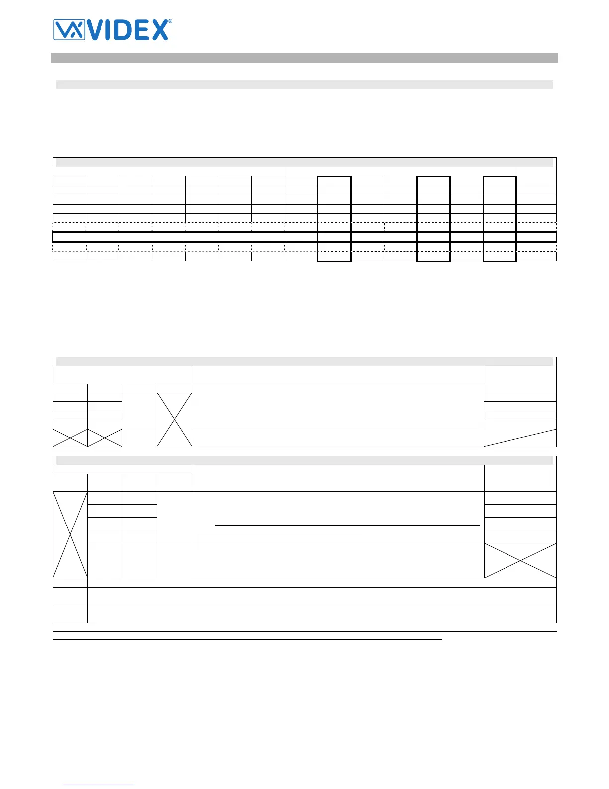
SW1 – VIDEOPHONE ADDRESS
Switches Status Binary Code – Decimal Weight
7 6 5 4 3 2 1 64 32 16 8 4 2 1
Address
OFF OFF OFF OFF OFF OFF ON 0 0 0 0 0 0 1 1
OFF OFF OFF OFF OFF ON OFF 0 0 0 0 0 1 0 2
OFF OFF OFF OFF OFF ON ON 0 0 0 0 0 1 1 3
OFF OFF OFF OFF ON OFF OFF 0 0 0 0 1 0 0 4
OFF ON OFF OFF ON OFF ON 0 1 0 0 1 0 1 37
ON ON OFF OFF OFF ON ON 1 1 0 0 0 1 1 99
The table above shows how to set the address of the videophone. Considering that ON = 1 and OFF = 0, multiply each digit for the relevant decimal
weight then sum values obtained to get the address: E.g. as highlighted in the table OFF,ON,OFF,OFF,ON, OFF,ON in binary is equal to 0100101 then
multiplying each digit for the relevant decimal weight you obtain the address that is 37.
Note
The maximum number of units allowed is 64 but the address of each unit can be a value between 1 and 99.
SW2 – PRIVACY DURATION TIME
Switches Status
Privacy Mode
(switch 2)
Privacy Duration
(switches 3,4)
4 3 2 1
OFF OFF 15 minutes
OFF ON 1 hour
ON OFF 4 hours
ON ON
OFF
The privacy duration time is set by the switches 3 and 4. After enabled the privacy
service is disable when the time set expire or the relevant button is pressed again.
8 hours
ON
No privacy time expiration: the privacy service is enabled or disabled only by the
relevant button.
SW3 – INTERCOMMUNICATION SETTINGS
Switches Status
4 3 2 1
Intercommunication Mode
(switch 1)
Videophone
Extension
(switches 2,3)
OFF OFF 1 (Master)
OFF ON 2 (Slave)
ON OFF 3 (Slave)
ON ON
OFF
Intercommunication allowed between videophones (same unit address) inside the
same flat. To call an extension pick up the handset then press the “door open” button
as many times as the extension value is (Eg. extension 2 two times, 3 three times
etc). If there are more videophones/intercoms connected in parallel, one at
least must be set with switches 2 and 3 to OFF
4 (Slave)
OFF OFF ON
Intercommunication allowed between videophones (different unit address) inside dif-
ferent flats. To call an extension pick up the handset then press the “door open” but-
ton as many times as the address value is (Eg. extension 10 ten times, 12 twelve
times etc)
Slave Mode (switch 4) for Extensions 2, 3 and 4
OFF Factory preset, during a call the videophone will ring only (while the master will show also the video) to show the video only if used to an-
swer.
ON During a call, the videophone will ring showing also the video: in this case the videophone must be powered locally using an Art.2321 and
connecting BUS+ to “Vin” (9) and BUS- to “–“ (10).
In case of more units (videophones or intercoms) in a parallel connection, apart from the status of switch 1 (intercommunication mode), the
extension programming must be always performed and the master unit (extension 1) must be always present.
 Loading...