10
Fig. 10
Abb. 10
10.1 10.2 10.3
Fig. 11
Abb. 11
11.1 11.2 11.3
Märklin K-Gleis
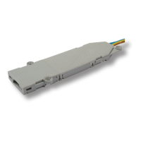
Hebel: 8 und 10
Montage: oberur, neben Gleis
1. Montieren Sie die Hebel gemäß Abb. 11.1 im Wei-
chenantrieb und verschließen Sie anschließend das
Gehäuse wieder.
2. Entfernen Sie den markierten Befestigungsring an der
Einkerbung mit einem scharfen Messer.
3. Bringen Sie die Weiche in die zum Antrieb passende
Stellung (Der Hebel des Weichenantriebs muss in den
Hebel der Weiche greifen).
4. Montieren Sie den Antrieb neben der Weiche (Abb.
11.2) und xieren Sie ihn mit den passenden Di-
stanzhülsen und Schrauben 2 x Nr. 13.
Märklin K-track
Lever: 8 and 10
Mounting: Overground, beside the track
1. Mountthelevers8and10asshowning.11.1into
the switch motor. After mounting the lever, close the
casing with the cover.
2. Cut off the fastening ring at the notch with a sharp
knifeasshowning.11.1.
3. Bring the turnout into the corresponding position of the
switch motor (the lever of the switch motor has to get
connected with the lever of the turnout).
4. Mount the switch motor beside the turnout as shown
ing.11.2.Fixtheswitchmotorwiththescrews2x
No. 13. Use the distance rolls!
Roco geoLINE
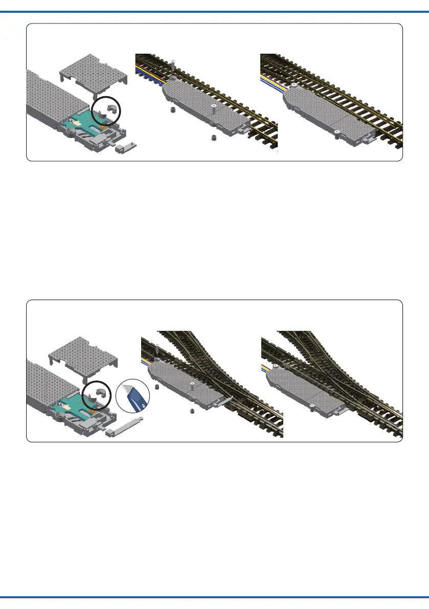
Hebel: 4 und 5
Montage: in Bettung
1. Stecken Sie den Draht gemäß Abb. in den Hebel.
Achten Sie auf Links- bzw. Rechtsweiche.
2. Montieren Sie den Hebel gemäß Abb. 12.1 im Wei-
chenantrieb und verschließen Sie anschließend das
Gehäuse wieder.
3. Entfernen Sie den Befestigungsring und die Träger-
platte (Abb. 12.1) mit einem scharfen Messer.
4. Bringen Sie die Weiche in die zum Antrieb passende
Stellung (Der Hebel des Weichenantriebs muss in den
Hebel der Weiche greifen).
5. Montieren Sie den Antrieb neben der Weiche (Abb.
12.2 und 12.3) und xieren Sie ihn mit einer pas-
senden Distanzhülse und Schraube 13.
Roco geoLINE
Lever: 4 and 5
Mounting: Into bed of ballast
1. Putthestealwire(5)intothelever(seeg.12.1).
Observe if it is a left or right turnout.
2. Mountlever4asshowning.12.1intotheswitchmo-
tor. After mounting the lever, close the casing with the
cover.
3. Cut off the plate and fastening ring beside the cable
outputwithasharpknifeasshowning.12.1.
4. Bring the turnout into the corresponding position of the
switch motor (the lever of the switch motor has to get
connected with the lever of the turnout).
5. Mount the switch motor beside the turnout as shown
ing.12.2and12.3.Fixtheswitchmotorwithascrew
No. 13. Use the distance roll!
 Loading...