6
Fig. 4
Abb. 4
4.1 4.2
Abb. 3
3.1 3.2 3.3
2,2 x 6 mm
2,2 x 6 mm
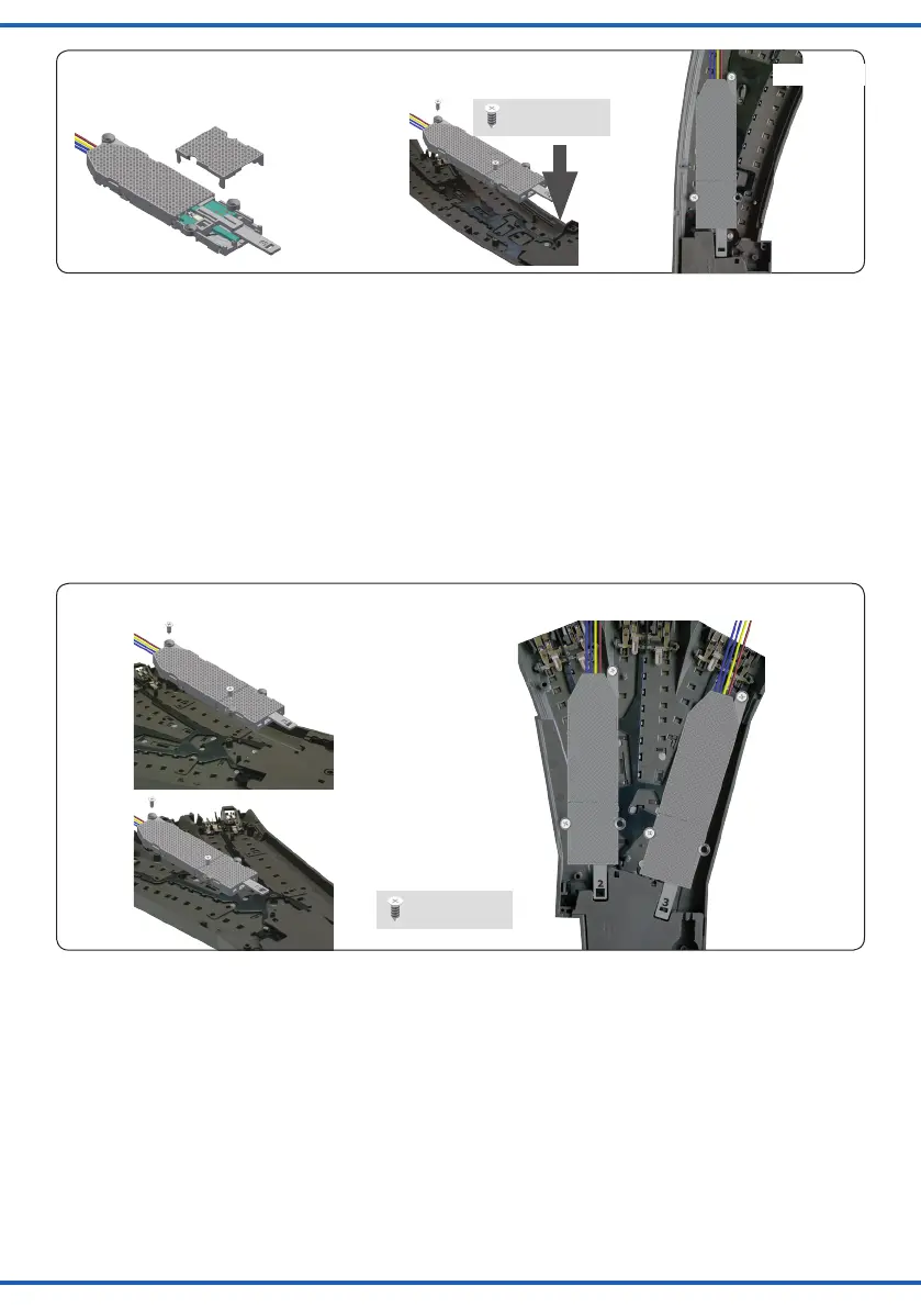
Fig. 3
Märklin C-Gleis (Dreiwegweiche)
Hebel: 2 und 3
Montage: in Bettung
Zum Antrieb der Dreiwegweiche benötigen Sie zwei
Viessmann Weichenantriebe.
1. Montieren Sie die beiden Hebel gemäß Abb. 3.1
(oben) in den Weichenantrieben und verschließen Sie
anschließend die Gehäuse wieder.
2. Bringen Sie die Weiche in die zu den Antrieben pas-
sende Stellung (Die Hebel der Weichenantriebe müs-
sen in die Hebel der Weiche greifen).
3. Legen Sie die Weichenantriebe gemäß Abb. 4.1 in die
Bettung der Weiche und xieren Sie sie mit den pas-
senden Schrauben 4 x Nr. 13 (Abb. 4.2).
Märklin C-track (three way turnout)
Lever: 2 and 3
Mounting: Into bed of ballast
To drive this turnout, you need two Viessmann switch mo-
tors (one for each turning).
1. Mountthetwoleversasshowning.3.1intothe
switch motor. After mounting the lever, close the cas-
ing with the cover.
2. Bring the turnout into the corresponding positions of
the switch motors (the levers of the switch motors
have to get connected with the levers of the turnout).
3. Put the switch motors into the intended empty space
oftheturnoutasshowning.4.1.
Fix the switch motors with the screws 4 x No. 13.
Märklin C-Gleis (DKW)
Hebel: 1
Montage: in Bettung
1. Montieren Sie den Hebel gemäß Abb. 3.1 (links) im
Weichenantrieb und verschließen Sie anschließend
das Gehäuse wieder.
2. Bringen Sie die Doppelkreuzungsweiche in die zum
Antrieb passende Stellung (Der Hebel des Weichen-
antriebs muss in den Hebel der DKW greifen).
3. Legen Sie den Weichenantrieb gemäß Abb. 5 in die
Bettung der Weiche und xieren Sie ihn mit den pas-
senden Schrauben 2 x Nr. 13.
Märklin C-track (double slip switch)
Lever: 1
Mounting: Into bed of ballast
1. Mountlever1asshowning.3.1intotheswitchmo-
tor. After mounting the lever, close the casing with the
cover.
2. Bring the switch into the corresponding position of the
switch motor (the lever of the switch motor has to get
connected with the lever of the switch).
3. Put the switch motor into the intended empty space of
theturnoutasshowning.5.
Fix the switch motor with the screws 2 x No. 13.
 Loading...