5
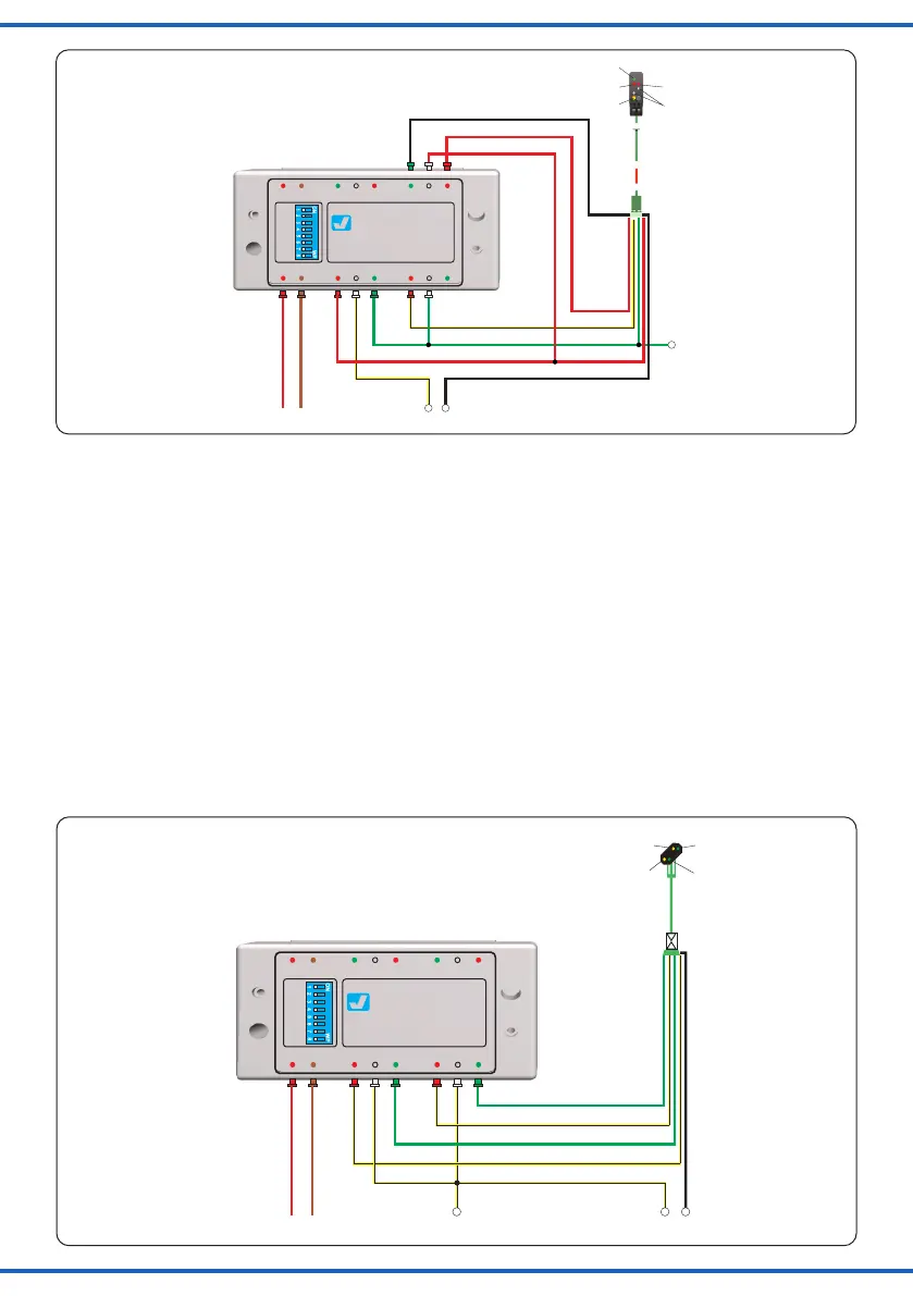
Fig. 4
Abb. 4
4
3
12
Adresse
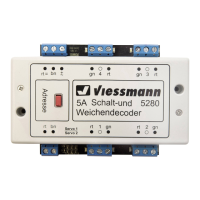
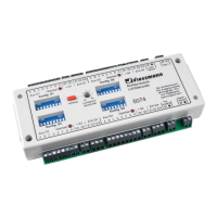
viessmann
Schaltdecoder 5213
rt2
ge
rt1
ws
gelb
yellow
braun
brown
rot
red
rot
red
rot/red
ws
gnrt1
ge
rt2
X*
16 V DC= / AC~
4416, 4913, 4916
grün/green
gelb/yellow
rot/red
rot/red
rot/red
Fig. 5
Abb. 5
vonderZentraleinheit
bzw.vomGleis
from the central unit
resp. from the track
4
3
12
Adresse
viessmann
Schaltdecoder 5213
X
16 V DC= / AC~
braun
brown
rot
red
gelb
yellow
gn2ge2
gn2
ge2
gn1
ge1
grün/green
gelb/yellow
grün
green
4016, 4410, 4414,
4415, 4416, 4910,
4915, 4916
Funktionen:
Taster1rot AusfahrsignalaufSh1/Hp00
Taster1grün AusfahrsignalaufHp1/Hp2
Taster2rot AusfahrsignalaufHp2(“Langsamfahrt“)
Taster2grün AusfahrsignalaufHp1(„Fahrt“)
Taster3rot AusfahrsignalaufHp00(„Halt“)
Taster3grün AusfahrsignalaufHp0/Sh1(„Rangierfahrt“)
Bemerkung:UmvonHp00oderHp0/Sh1nachHp1
oderHp2zuschalten,zuerstmitdemTastenpaar2Hp1
oderHp2bzw.mitdemTastenpaar3Hp00oderHp0/Sh1
vorwählen.ErstdanneinederTasten1(grünoderrot)
betätigen!
Functions:
Button 1 red exit signal to Hp00 / Sh1
Button 1 green exit signal to Hp1 / Hp2
Button 2 red exit signal to Hp2 (“reduced speed“)
Button 2 green exit signal to Hp1 (“go“)
Button 3 red exit signal to Hp00 (“stop“)
Button 3 green exit signal to Hp0/Sh1 (“shunting maneuver“)
Remark: To switch from Hp00 or Hp0/Sh1 to Hp1 or Hp2
please choose at first between Hp1 and Hp2 with the
button pair 2 resp. between Hp00 and Hp0/Sh1 with the
button pair 2. After this push one of the buttons 1 (green
or red)!
vonderZentraleinheit
bzw.vomGleis
from the central unit
resp. from the track
Ausfahrsignal(4Begrie)
Exit Signal (4 aspects)
Vorsignal(3Begriffe)
Distant signal (3 aspects)