6
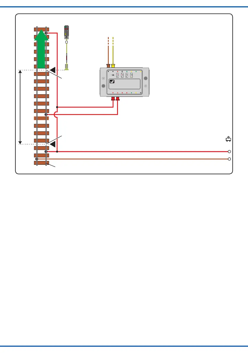
Fahrstrom
traction
current
ca. 2 Loklängen
approx. 2 locomotive lengths
direction of
travel
entspricht dem Mittelleiter bei Märklin-Schienen
corresponds to the of M rklin tracksneutral conductor ä
N2
Fahrtrichtung
Trennstelle
disconnecting
5223
16 V~AC
rt1
ws
zum Gleis
gn
Vorsignal -
Steuerung
rt2
viessmann
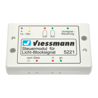
Steuermodul für
Licht-Ausfahrsignal
5223
16 V
bn ge
ge
point
Trennstelle
disconnecting
point
Fig. 6
Abb. 6
4. Steuermodul und Weiche
Das Signalbild Hp2 („Langsamfahrt“) wird geschaltet,
wenn mindestens eine der folgenden Weichen auf „ab-
zweigen“ gestellt ist. Abb. 7 zeigt, wie Steuermodul und
Weiche gemeinsam geschaltet werden können.
5. Digitale Ansteuerung
Sie können das Steuermodul für Licht-Ausfahrsignale
auch mit einem Digitalsystem über einen Magnetartikel-
decoder (z. B. Art.-Nr. 5211 für Märklin-Motorola-Format
oder 5280 für das NMRA- und DCC-Format) ansteuern
(Abb. 8). Wichtig ist, dass der Magnetartikeldecoder
positive Schaltimpulse liefert (d. h. er schaltet gegen „+“)!
Außerdem muss bei Art.-Nr. 5211 eine Verbindung zwi-
schen Digital-Masse (braun) und Masse der 16 V-Versor-
gungsspannung des Steuermoduls (braun) hergestellt
werden. Bei Art.-Nr. 5280 beachten Sie die markierte
Verbindung in Abb. 8.
Alternativ können sie auch das Steuermodul für Licht-
Signale Art.-Nr. 5224 verwenden. Dort ist ein Digitalde-
coder bereits integriert!
5. Control module and point
The signal has to show the Hp2 aspect (“proceed at re-
duced speed”) if minimum one of the following turnouts is
set to “branch o”. Fig. 7 shows how you can switch the
control module and the point together.
6. Digital control
The control module for colour light departure signals can
also be operated with a digital system. Simply connect the
cables to an accessory decoder (e. g. item-No. 5211 for
Märklin-Motorola format or 5280 for the NMRA and DCC
format). Also refer to g. 8. It is important to know, that the
pulses supplied by the accessory decoder have positive
potential (the decoder switches against “+”)! With item-No.
5211 the common pole of the digital circuit (brown) must be
connected with the common pole of the 16 V supply for the
control module (brown). With item-No 5280 please consider
to the marked connection in g. 8.
Alternatively you can use item-No. 5224 digital control
module for colour light signals. The digital decoder is
already integrated.