19
Name der CV
Name of CV
CV-
Nr.
No.
Eingabewerte
(Default)
value range
Erläuterungen/Hinweise
Remarks
Adresse
Address
1 0 ... 63 (1) Enthält die unteren 6 Bit der Decoderadresse.
Zusammen mit CV 9 wird so die Adresse
gespeichert. Adresse 1 = Ausgang 1, 2, 3, 4;
Adresse 2 = Ausgang 5, 6, 7, 8 usw.
Contains the lower 6 bits of the
decoder address. Thus the address
is saved in conjunction with CV 9.
Address 1 = output 1, 2, 3, 4;
Address 2 = outputs 5, 6, 7, 8 etc.
Ausgänge aktiv
Outputs active
2 0 ... 255 (255)
Man kann die einzelnen Ausgänge deaktivieren.
Bit 0 (Wert 1): Ausgang 1 rot erlaubt
Bit 1 (Wert 2): Ausgang 1 grün erlaubt
Bit 2 (Wert 4): Ausgang 2 rot erlaubt usw.
Z. B. Wert = 205 (binär 11001101) bedeutet,
dass bei Ausgang 1 nur rot aktiv ist und
Ausgang 3 komplett deaktiviert ist.
Used to deactivate individual outputs.
Bit 0 (value 1): output 1 red enabled
Bit 1 (value 2): output 1 green enabled
Bit 2 (value 4): output 2 red enabled
etc. For example, value 205 (binary
11001101) means that output 1 has
only red active, and output 3 is com-
pletely disabled.
Konguration Ausgang 1
Conguration output 1
3 0 ... 99 (1) Wert 0: Momentbetrieb: Ausgang ist so lange
aktiv, wie die Taste am Bedienpult gedrückt
wird (mind. 100 ms).
Wert 1: Begrenzter Momentbetrieb: Ausgang
ist so lange aktiv, wie die Taste am Bedien-
pult gedrückt wird (mind. 100 ms), mit einer
maximalen Zeit von 2 Sekunden (Grundein-
stellung).
Werte 2 – 50: Impulsbetrieb (Momentbetrieb
mit festen Impulsen). Ausgang für (Wert -1) x
100 ms aktiv, egal, wie lange der Befehl ist.
Werte 51 – 90: Wechselblinken: Ausgang
grün und rot abwechselnd aktiv, wenn das
Ausgangspaar auf grün (aktiv) geschaltet ist
(CV 2). Periode: (Wert - 50) x 100 ms.
Wert 91: Bistabiler Dauerbetrieb: Entweder
Ausgang grün oder rot aktiv, Dauerausgang.
Wert 92: Bistabiler Dauerbetrieb, mehrbe-
grig: Ausgang schaltet aus, wenn das Nach-
barausgangspaar einen Befehl bekommt.
Damit kann man mehrbegrige Lichtsignale
steuern. Z. B. CV 3 = 92 und CV 4 = 92: Jetzt
gehören Ausgänge 1 und 2 zusammen, man
kann z. B. ein Ausfahrsignal anschließen.
Der Decoder sorgt dafür, dass nur ein Begri
gleichzeitig sichtbar ist.
Verwendung für Lichtsignalsteuerung:
Negativ geschaltet (z. B. herkömmliche
Viessmann Lichtsignale):
Wert 91: Herkömmliche 2-begrige Signale,
z. B. Blocksignal.
Wert 92: 3-begriges Einfahrsignal, zweite
Adresse grün schaltet Hp2.
Wert 93: 4-begriges Ausfahrsignal, zweite
Adresse rot schaltet Sh1.
Wert 94: 4-begriges Ausfahrsignal, zweite
Adresse rot schaltet Hp2.
Positiv geschaltet, z. B. Signale anderer Her-
steller oder selbst gebastelte Signale, deren
Masse gemeinsam ist.
Werte 95 – 98: Analog zu 91 – 94.
Value 0: Momentary action mode: Out-
put is active as long as the respective
button on the panel is pressed (100 ms
minimum).
Value 1: Limited momentary action
mode: Output is active as long as the re
-
spective button on the panel is pressed
(100 ms minimum) and a maximum of 2
seconds (default setting).
Values 2 – 50: Pulse mode (momen-
tary action mode with predetermined
pulses). Output for (value -1) x 100 ms
active, regardless of the duration of the
command.
Values 51 – 90: Alternate blinking:
Green and red output alternately ac
-
tive, if and when the output pair is set
to green (active) (CV 2). Period: (value
- 50) x 100 ms.
Value 91: Flip-op continuous mode:
Either the red or the green output is ac
-
tive continuously.
Value 92: Bistable continuous mode,
multi-aspect: Output turns o if the
neighbouring output pair receives a
command. This allows you to control
multi-aspect colour light signals. E. g.
CV 3 = 92 and CV 4 = 92: Now outputs
1 and 2 are linked. This facilitates con
-
trol of an departure signal, amongst
others. The decoder assures that only
one aspect is displayed at any time.
Controlling colour light signals:
Negative logic (common Viessmann
light signals):
Value 91: 2-aspect signals, for example
block signals.
Value 92: 3-aspect entry signal, sec-
ondary adress green means Hp2.
Value 93: 4-aspect departure signal,
secondary address red means shunting
Value 94: 4-aspect departure signal,
secondary address red means speed
limit.
Positive logic (colour light signals which
use a common ground).
Values 95-98: Similar to 91 – 94.
Konguration Ausgang 2
Conguration output 2
4 0 ... 99 (1)
Konguration Ausgang 3
Conguration output 3
5 0 ... 99 (1)
Konguration Ausgang 4
Conguration output 4
6 0 ... 99 (1)
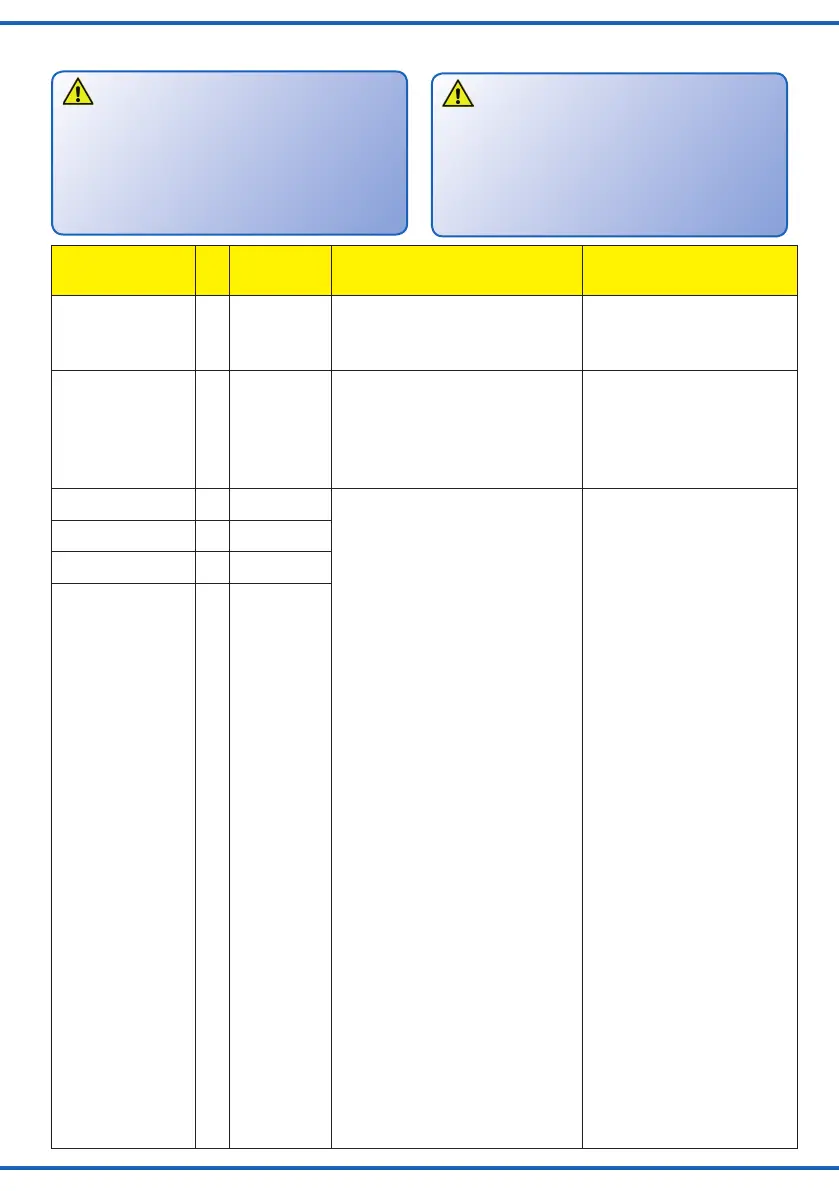
7. CV-Tabelle
7. CV table
Für einige Kongurationsvariablen werden
die Eingabewerte durch Addieren der Zahlen-
werte ermittelt, die den gewünschten Einstel-
lungen entsprechen. Diese sogenannten Bit-
basierten Zahlen sind in Spalte 3 der Tabelle
kursiv dargestellt.
Hinweis:
For some conguration variables the values
to be entered are determined by adding the
corresponding numbers to the desired
settings.These bit-based variables are indi-
cated by italic type in column 3 of the table.
Note:
 Loading...