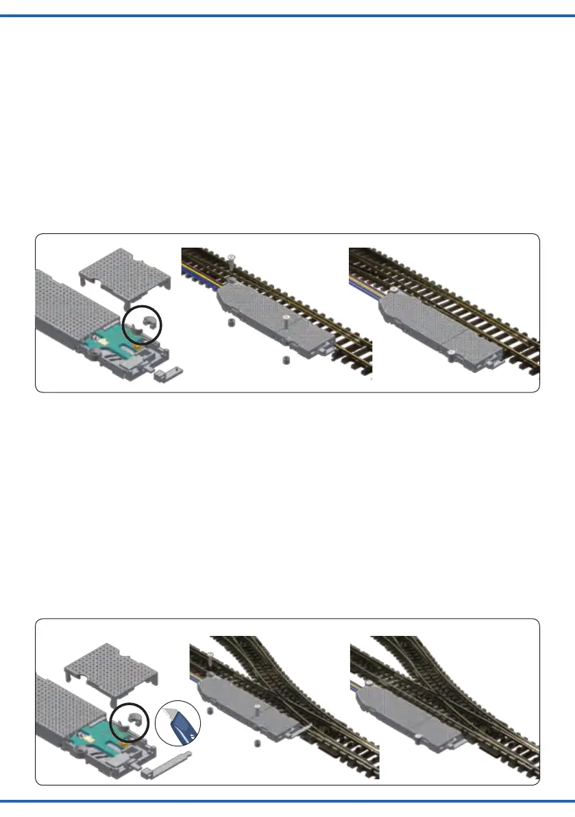
Fig. 10
Abb. 10
10.1 10.2 10.3
Fig. 11
Abb. 11
11.1 11.2 11.3
Tillig H0 Elite
Hebel: 8 und 11
Montage: oberur,nebenGleis
1. Montieren Sie die Hebel gemäß Abbildung 10.1 im
Weichenantrieb und verschließen Sie anschließend
das Gehäuse wieder.
2. Entfernen Sie den markierten Befestigungsring an der
Einkerbung mit einem scharfen Messer.
3. Bringen Sie die Weiche in die zum Antrieb passende
Stellung (Der Hebel des Weichenantriebs muss in den
Hebel der Weiche greifen).
4. Montieren Sie den Antrieb neben der Weiche (Abb.
10.2)undxierenSieihnmitdenpassendenDi-
stanzhülsen und Schrauben 2 x Nr. 13.
Märklin K-Gleis
Hebel: 8 und 10
Montage: oberur,nebenGleis
1. Montieren Sie die Hebel gemäß Abbildung 11.1 im
Weichenantrieb und verschließen Sie anschließend
das Gehäuse wieder.
2. Entfernen Sie den markierten Befestigungsring an der
Einkerbung mit einem scharfen Messer.
3. Bringen Sie die Weiche in die zum Antrieb passende
Stellung (Der Hebel des Weichenantriebs muss in den
Hebel der Weiche greifen).
4. Montieren Sie den Antrieb neben der Weiche (Abb.
11.2)undxierenSieihnmitdenpassendenDi-
stanzhülsen und Schrauben 2 x Nr. 13.
Tillig H0 Elite
Lever: 8 and 11
Mounting: Overground, beside the track
1. Mount levers 8 and 11 as shown in gure 10.1 into the
switch motor. After mounting the lever, close the cas-
ing with the cover.
2. Cut off the fastening ring at the notch with a sharp
knife as shown in gure 10.1.
3. Bring the turnout into the corresponding position of the
switch motor (the lever of the switch motor has to get
connected with the lever of the turnout).
4. Mount the switch motor beside the turnout as shown
in gure 10.2. Fix the switch motor with the screws 2 x
nr. 13. Use the distance rolls!
Märklin K-track
Lever: 8 and 10
Mounting: Overground, beside the track
1. Mount the levers 8 and 10 as shown in gure 11.1 into
the switch motor. After mounting the lever, close the
casing with the cover.
2. Cut off the fastening ring at the notch with a sharp
knife as shown in gure 11.1.
3. Bring the turnout into the corresponding position of the
switch motor (the lever of the switch motor has to get
connected with the lever of the turnout).
4. Mount the switch motor beside the turnout as shown
in gure 11.2. Fix the switch motor with the screws 2 x
nr. 13. Use the distance rolls!


 To Next Page