8
In a 1-phase power circuit
S
1 2 3 4 5 6 7
8 9 10
1112
13
14
1516
17
181920
2122
23
24
2526
N
L1 L2
L3
L1
N
K
L
A
230 V~
B
C
D
K
L
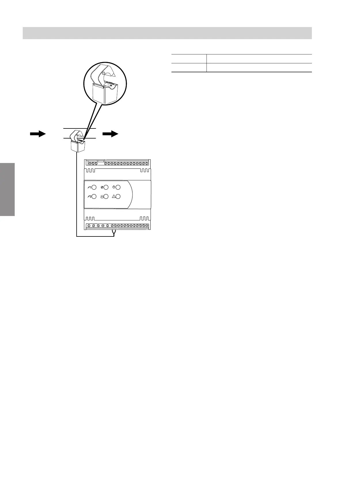
Fig. 3
A
From the main electricity meter
B
To the RCD
C
Current sensor with 3 m connecting cable (energy
meter standard delivery)
D
Energy meter
Core assignment
1 Red
2 Black
Connect current sensors in the correct position, as
shown in fig. 3:
■
Green point facing in the direction of the RCD
■
Arrow of the "K Ó L" imprint (on the inside of current
sensor clip) pointing in the direction of the RCD
Electrical connections
Connecting the current sensors
5678 581 GB
Service