11
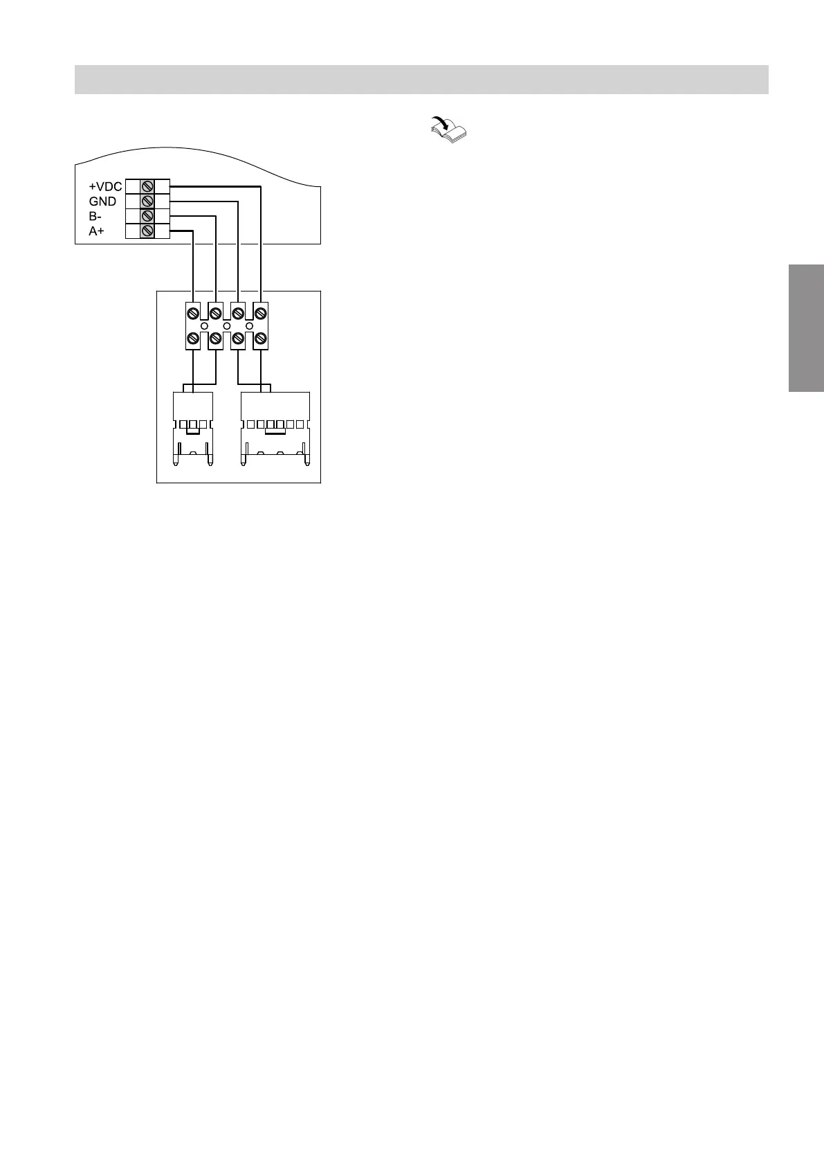
Connecting the connecting cable
A
4 3 2 1
H
B
C F
E
GN YE WH BN
GN YE WH BN
Fig. 3
A
Ventilation programming unit, type LB1
B
Control PCBVitovent 200-C
C
Modbus plug, connection J9 to control PCB
Vitovent 200-C
E
Luster terminals
F
Power supply plug, connection J4 to control PCB
Vitovent 200-C
H
Connection terminals for ventilation programming
unit, type LB1
Installation and service instructions
"Vitovent 200-C"
Installation sequence
Electrical connections (cont.)
5816558
Installation