10
Vitovent 200-C: Connecting the connecting cable
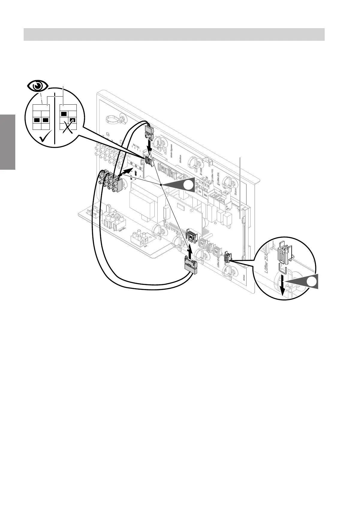
Connect the supplied connecting cable to the Vitovent 200-C control PCB
F
E
C
1.
2.
1 2
ON
1 2
ON
YE
GN
WH
BN
D
B
G
Fig. 2
B
Control PCBVitovent 200-C
C
Modbus plug, connection J9 to control PCB
Vitovent 200-C
D
DIP switch
E
Luster terminals
F
Power supply plug, connection J4 to control PCB
Vitovent 200-C
G
Jumper
2.
Remove jumper
G
.
!
Please note
If jumper
G
is installed and/or the DIP
switches are incorrectly set, the ventilation
unit will not operate.
■
Remove jumper
G
.
■
Set DIP switch
D
according to Fig. 2.
Installation sequence
Electrical connections (cont.)
5816558
Installation