10
Danger
Incorrect wiring can lead to serious injury from
electrical current and result in appliance dam-
age.
■
Route extra low voltage (ELV) leads < 42 V
and > 42 V/230 V~ cables separately.
■
Only strip the minimum of insulation from
cables as close as possible to the terminals
and bundle tightly to the corresponding termi-
nals.
■
Secure cables with cable ties.
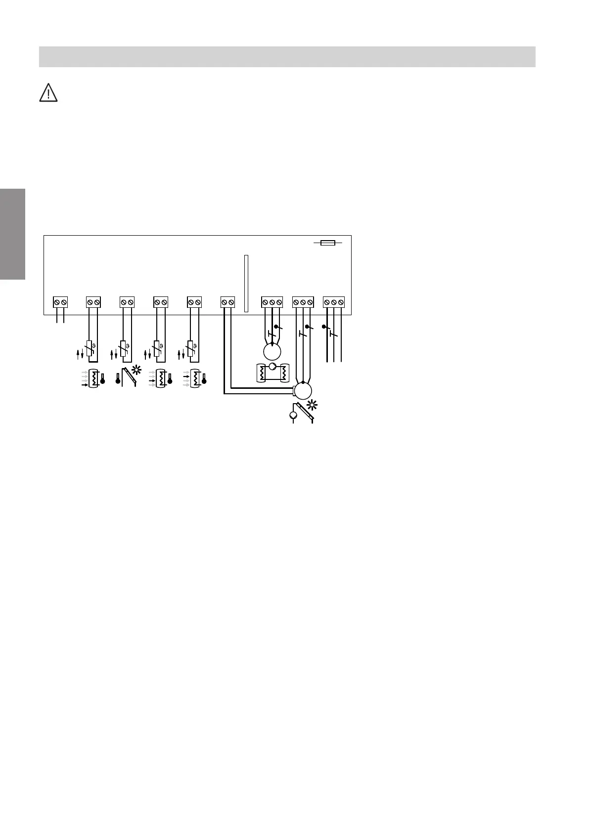
SDIO/SM1A electronics module
% &aVG
[{]
PWM
L
?
N
L
?
N
sF fÖ
M
1~
/ aÖ
L
?
N
M
1~
sS
230 V∼
jF
aVG
KM-BUS
jF
PLUS-
BUS
50 Hz
F1 T 2 A
SDIO/SM1A
TS1 TS2 TS3 TS4
Fig. 1
%
Cylinder temperature sensor, NTC 10 kΩ (TS1,
standard delivery) with plug
%
&
Collector temperature sensor, NTC 20 kΩ (TS2,
standard delivery)
/
Temperature sensor, NTC 10 kΩ (TS3, standard
delivery)
aÖ
Temperature sensor, NTC 10 kΩ (TS4, standard
delivery)
sS
Transfer pump or 3-way diverter valve
sF
Solar circuit pump (only with PWM signal)
fÖ
Power supply
jF
PlusBus for connection to the HMU heat man-
agement unit, DIO electronics module or ADIO
electronics module
aVG
KM-BUS for connection to the Vitotronic boiler
control unit
PWM Solar circuit pump speed control
!
Please note
Electronic assemblies can be damaged by static
loads.
Before beginning work, touch an earthed object
such as a heating or water pipe to discharge any
static.
Note
Apply strain relief to on-site cables.
Seal any unnecessary apertures with cable grommets
(not cut open).
Installation sequence
Overview of electrical connections
6131981
Installation