38
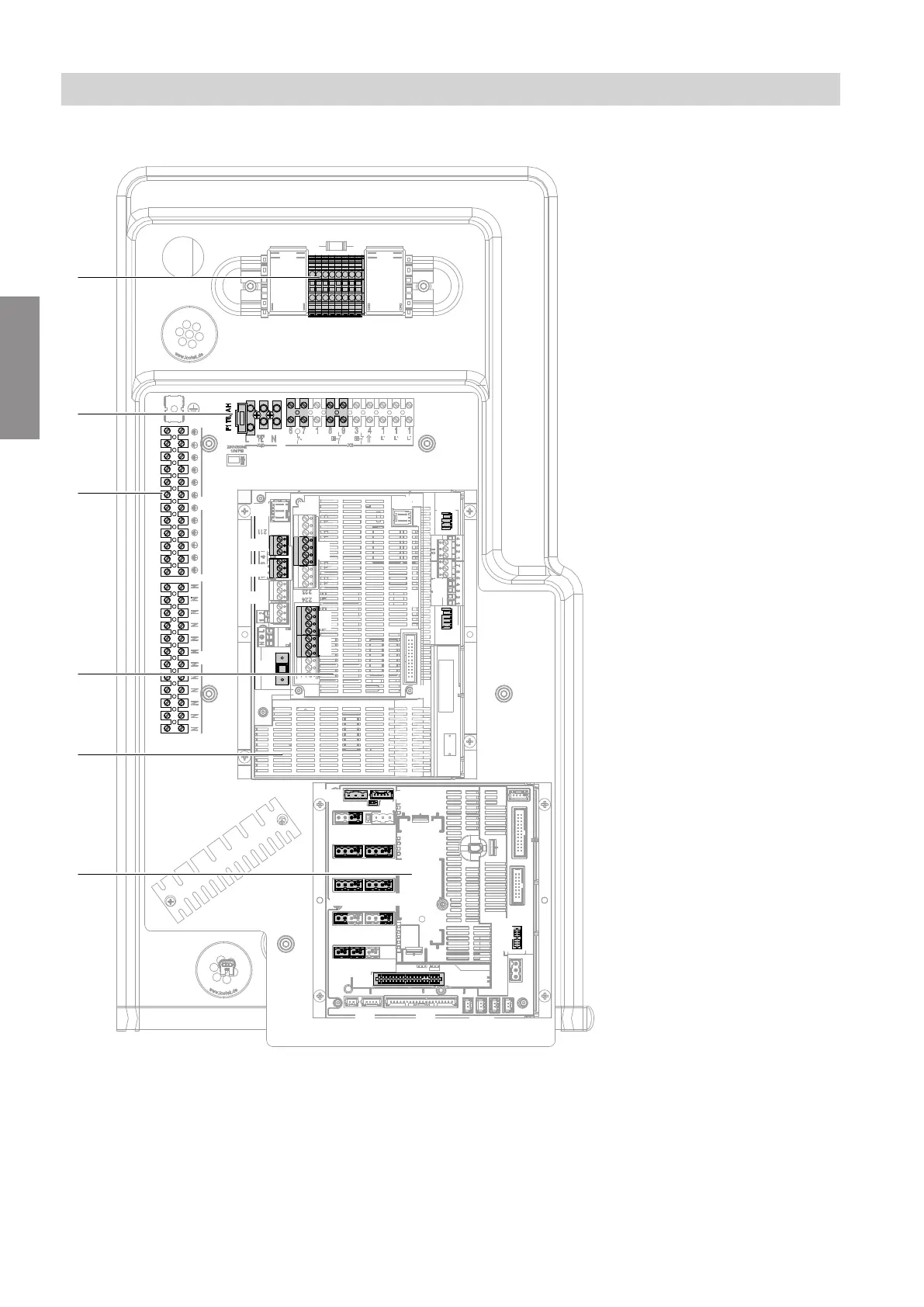
Indoor unit: Overview of connections
G
216
210
211
221
213
224
214
215
220
X2
X1
X1
40
212
X3
222
225
F16F14
X18
J1
F13
F11
F4
145
F0
X24
X31
F12
F7
F20F21
F6
F8
F27
F26F23
J4
J3
X25X15
193A
241
X1 X2
F3
A
B
C
D
F
E
Fig. 33
A
If available:
Switching module and power supply for instanta-
neous heating water heater: See page 53
onwards.
B
Heat pump control unit power supply 230 V~: See
page 52.
F1 Fuse 6.3 A (slow)
C
Luster terminals: See page 45.
X1 Terminals for protective conductors of all asso-
ciated system components
X2 Terminals for neutral conductors of all associ-
ated system components
D
Expansion PCB on main PCB: See page 42.
Installation sequence
Electrical connection (cont.)
6199585
Installation
 Loading...